


Page 24
CAUTION
If this unit is being installed in an application with
combustion air coming in from a space serviced by
an exhaust fan, power exhaust fan, or other device
which may create a negative pressure in the space,
take care when sizing the inlet air opening. The in
let air opening must be sized to accommodate the
maximum volume of exhausted air as well as the
maximum volume of combustion air required for
all gas appliances serviced by this space.
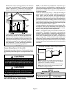
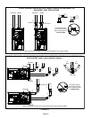
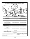
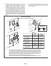
FIGURE 28
EQUIPMENT IN CONFINED SPACE
(Inlet Air from Ventilated Attic and Outlet Air to Outside)
NOTE-The inlet and outlet air openings shall each have a free area
of at least one square inch per 4,000 Btu (645mm
2
per 1.17kW) per
hour of the total input rating of all equipment in the enclosure.
Ventilation Louvers
Inlet Air
(Minimum
12 in.(305mm) Abov
e
attic floor)
Roof Terminated
Exhaust Pipe
Furnace
*Intake Debris
Screen
(Provided)
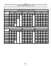
* See table 6 for maximum vent lengths
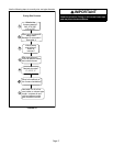
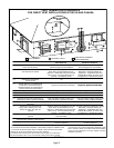
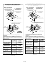
FIGURE 29
NOTE-The inlet and outlet air openings shall each have a free area
of at least one square inch per 4,000 Btu (645mm
2
per 1.17kW) per
hour of the total input rating of all equipment in the enclosure.
EQUIPMENT IN CONFINED SPACE
(Inlet Air from Ventilated Crawlspace and Outlet Air to Outside)
Roof Terminated
Exhaust Pipe
Furnace
Ventilation
Louvers
(Crawl space)
*Intake Debris Screen Provided)
Inlet Air
(Minimum
12 in.(305mm)
Above crawl
space floor)
Coupling or
3 in. to 2 in.
Transition
(Field Provided)
* See table 6 for maximum vent lengths
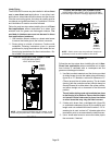
General Guidelines for Vent Terminations
In Non‐Direct Vent applications, combustion air is taken
from indoors or ventilated attic or crawlspace and the flue
gases are discharged to the outdoors. The EL296UHE is
then classified as a non‐direct vent, Category IV gas fur
nace.
In Direct Vent applications, combustion air is taken from
outdoors and the flue gases are discharged to the out
doors. The EL296UHE is then classified as a direct vent,
Category IV gas furnace.
In both Non‐Direct Vent and Direct Vent applications, the
vent termination is limited by local building codes. In the
absence of local codes, refer to the current National Fuel
Gas Code ANSI Z223-1/NFPA 54 in U.S.A., and current
CSA-B149 Natural Gas and Propane Installation Codes in
Canada for details.
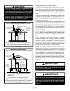
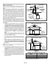
Position termination according to location given in figure 30
or 31. In addition, position termination so it is free from any
obstructions and 12” above the average snow accumula
tion.
At vent termination, care must be taken to maintain
protective coatings over building materials (prolonged
exposure to exhaust condensate can destroy protective
coatings). It is recommended that the exhaust outlet not be
located within 6 feet (1.8m) of a condensing unit because
the condensate can damage the painted coating.
NOTE - See table 7 for maximum allowed exhaust pipe
length without insulation in unconditioned space during
winter design temperatures below 32°F (0°C). If required
exhaust pipe should be insulated with 1/2” (13mm) Arma
flex or equivalent. In extreme cold climate areas, 3/4”
(19mm) Armaflex or equivalent may be necessary. Insula
tion on outside runs of exhaust pipe must be painted or
wrapped to protect insulation from deterioration. Exhaust
pipe insulation may not be necessary in some specific ap
plications.
IMPORTANT
Do not use screens or perforated metal in exhaust
terminations. Doing so will cause freeze-ups and
may block the terminations.
IMPORTANT
For Canadian Installations Only:
In accordance to CSA International B149 installation
codes, the minimum allowed distance between the
combustion air intake inlet and the exhaust outlet of
other appliances shall not be less than 12 inches
(305mm).