


Page 35
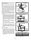
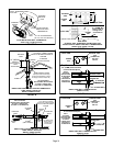
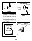
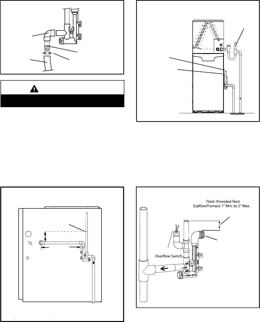
FIGURE 52
Tubing
Hose Clamp
Barbed Fitting
Field Provided Drain Components
Elbow
CAUTION
Do not use copper tubing or existing copper conden
sate lines for drain line.
6 - If unit will be started immediately upon completion of
installation, prime trap per procedure outlined in Unit
Start-Up section.
Condensate line must slope downward away from the
trap to drain. If drain level is above condensate trap,
condensate pump must be used. Condensate drain
line should be routed within the conditioned space to
avoid freezing of condensate and blockage of drain
line. If this is not possible, a heat cable kit may be used
on the condensate trap and line. Heating cable kit is
available from Lennox in various lengths; 6 ft. (1.8m) -
kit no. 26K68; 24 ft. (7.3m) - kit no. 26K69; and 50 ft.
(15.2m) - kit no. 26K70.
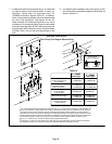
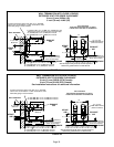
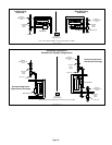
FIGURE 53
(Unit shown in upflow position with remote trap)
*5’ max.
To Drain
PVCPipeOnly
FieldProvidedVent
Min.1”AboveCondensate
Drain
Connection
1”
Min.
2”Max.
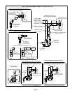
CONDENSATE TRAP LOCATIONS
Trap can be installed a
maximum 5' from furnace
*Piping from furnace must slope down a minimum of
1/4” per ft. toward trap.
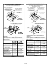
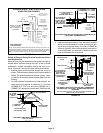
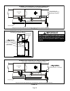
FIGURE 54
EL296UHE With Evaporator
Coil Using A Separate Drain
Condensate
Drain
Connection
Field Provided Vent
(1” min. 2” max. above
condensate connection)
Evaporator drain
line required
FIGURE 55
Horizontal Furnace
4”
Min.to 5”Max.above
condensate drainconnection)
FurnaceCondensate
DrainConnection
From Evaporator Coil
Optional
Condensate Trap With Optional Overflow Switch