


30
OPERATION OF THE SYSTEM WTC 600 LP / MP
Service Handbook 08.2004
3.3.2.4 Float Switch
Connect the signal lines of the enclosed float switch to clamps 6/7 (8S3 option) of the
connecting terminal – compare wiring diagram in the switching box. Upon installation, adjust a
switching hysteresis of at least 300 liters between the switching-on and switching-off point.
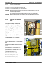
3.3.2.5 Reverse Osmosis System
The WTC 600 LP/MP is connected to the following power supply:
- 400 V / 50Hz, 3Ph + N + PE or 230 V / 50Hz, 1Ph + N + PE (depending on type of system)
- Fuse protection 16 A
- RC protective switch 30 mA from source of power supply (check if in existence or have
confirmed in writing).
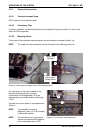
3.4 Starting Operation
Operation of the individual equipment components is started in the following sequence:
- Fill the preliminary filter and start operation by backwashing (3.4.2)
- De-conserve reverse osmosis (3.4.3.7)
- Fill metering container and start operation (3.4.1)
- Start the operation of the reverse osmosis (3.4.3.8)
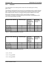
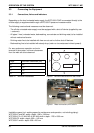
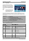
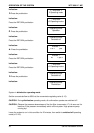
3.4.1 Metering Station
Pushbutton for venting in “continuous operation” (14/3).
Operating mode on “Manual” (14/2)!
Change the operating mode by pressing the
"Mode" key (14/2).
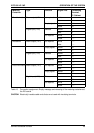
Modul Lift Frequency Meter-
(14/1) (14/4) ing
Pre-
chlorination 40% 70% 3.2.2
Antiscalant 40% 50% 3.2.3
Post
clorination 40% 70% 3.2.4
Flocculation 40% 70% 3.2.5
Table 14 Checking pump settings
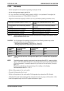
Adjust the lift only when the
pump is running. Danger of
damaging!
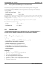
Figure 14 Metering station
2
1
4
3
NOTE
NOTE