28
OPERATION OF THE SYSTEM WTC 600 LP / MP
Service Handbook 08.2004
3.3.2 Electrical Connections
3.3.2.1 Pressure-increase Pump
230 V external, via connection cable.
3.3.2.2 Preliminary Filter
In delivery condition, the preliminary filters are connected to the power outlets (1/f) on the rear
side of the RO equipment.
3.3.2.3 Metering Station
The pumps of the projected metering stations are connected to the power outlets (1/g).
The cable from the float switch must be inserted in the metering pump unit.
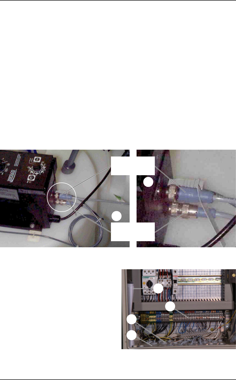
Figure 12 Alarm output and digital input of the metering pumps
Alarm output
(empty alarm)
Digital input
(release)
For connection of the control cables in the
electrical switching cabinet, the blind
connections in the flange plate (13/4) are
replaced by the enclosed cable screw fittings
(13/3).
Connect the control cables in accordance with
Table 13.
The complete connecting
diagrams / plans (13/1) are located
in the switch cabinet.
The connections for signal inputs
that are not required are bridged at
the connecting terminal (13/2).
Figure 13 Connections, metering stations
2
1
4
3
2
1
NOTE
NOTE
NOTE


