


27
WTC 600 LP / MP OPERATION OF THE SYSTEM
Service Handbook 08.2004
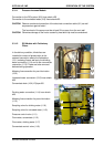
3.3.1.1 Pressure-increase Module
Connection to the RO system (9/2) Hose shank d25
Connection to the untreated water (9/3) Hose shank d25
Observe mechanical protection of the electrical connection cable (9/1) as well
as protection against water!
The fan wheel of the pump must be at least 20 cm away from the next wall.
Otherwise damage to the motor caused by heat build-up must be considered.
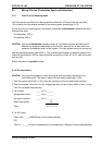
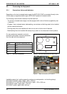
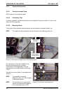
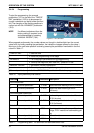
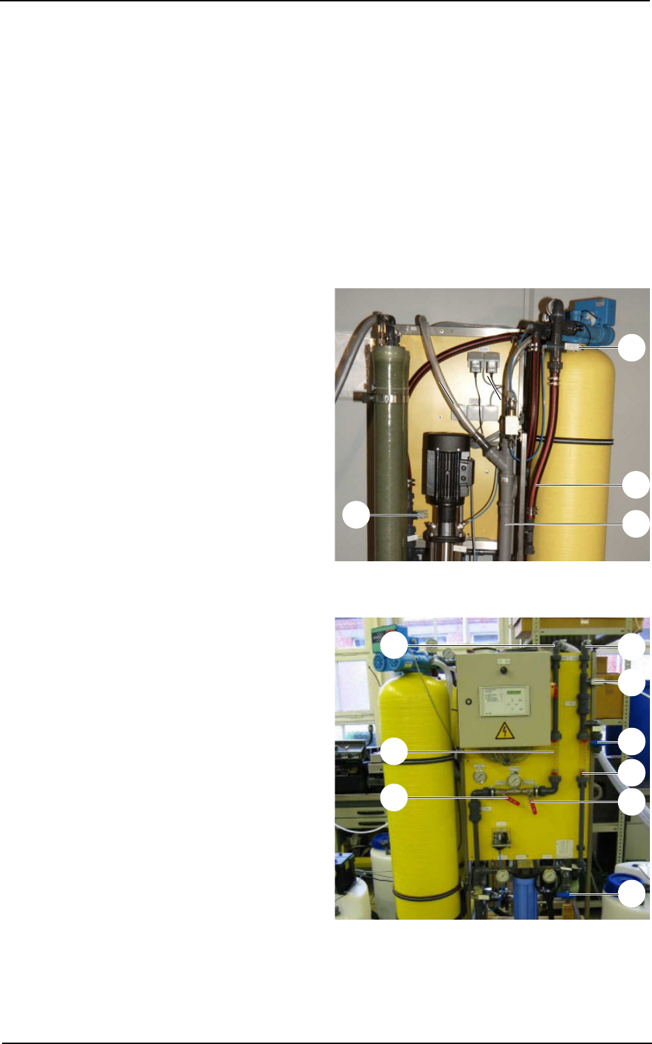
3.3.1.2 RO Module with Preliminary
Filters
In the delivery condition, blind discs are
installed for means of preservation to the
screwed connection above the Antiscalant
(10/1) metering line as well as to the drinking
water connection (11/4) and to the concentrate
connection (11/3). These are to be removed
before starting operation.
Metering line connection for pre-chlorination
(10/2)
Untreated water connection (10/3) hose shank
d25
Concentrate drain (10/4) HT-pipe d50
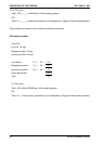
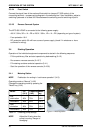
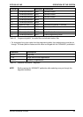
Drinking water connection (11/4) hose shank
d25
Metering line connection for post chlorination
(11/5)
Sampling valve for drinking water (11/6)
Sampling valve for untreated water (11/9)
Pressure control valve (11/1)
Flow meter, concentrate (11/2)
Flow meter, drinking water (11/7)
Concentrate control valve (11/8)
Figure 10 Connections, rear
Figure 11 Connections, front
2
1
4
3
2
1
4
3
5
6
7
8
9
CAUTION
CAUTION