


8
classic HE - Installation & Servicing
GENERAL
Bathrooms
This range of appliances is rated IP 1XB.
The boiler may be installed in any room or internal space, although
particular attention is drawn to the requirements of the current
I.E.E. (BS.7671) Wiring Regulations and, in Scotland, the electrical
provisions of the building regulations applicable in Scotland with
respect to the installation of the boiler in a room or internal space
containing a bath or shower. For Ireland reference should be
made to the current ETCI rules for electrical installations and
I.S.813:2002.
If the appliance is to be installed in a room containing a bath or
shower then, providing waterjets are not going to be used for
cleaning purposes (such as communal baths/showers), the
appliance can be installed in Zone 3, as detailed in BS.7671.
Where installation will be in an unusual location, special
procedures may be necessary and BS.6798 gives detailed
guidance on this aspect.
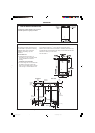
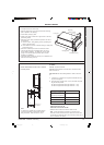
Compartment Installations
A compartment used to enclose the boiler MUST be designed
and constructed specially for this purpose.
An existing cupboard or compartment may be used, provided it
is modified for the purpose.
In both cases details of essential features of cupboards/
compartment design, including airing cupboard installation, are
to conform to the following :
z BS. 6798.
z The position selected for installation MUST allow adequate
space for servicing in front of the boiler and for air circulation
around the boiler. Refer to 'Air Supply'.
z For the minimum clearances required for safety and
subsequent service refer to the wall mounting diagram,
Frame 2. In addition, sufficient space may be required to allow
lifting access to the wall mounting plate.
GAS SUPPLY
The local gas supplier should be consulted, at the installation
planning stage, in order to establish the availability of an adequate
supply of gas. An existing service pipe must NOT be used without
prior consultation with the local gas supplier.
The boiler is to be installed only on a gas supply with a governed meter.
A gas meter can only be connected by the local gas supplier or by
a local regional contractor.
An existing meter should be checked, preferably by the gas supplier,
to ensure that the meter is adequate to deal with the rate of gas
supply required. A MINIMUM pressure of 20 mbar MUST be
available at the boiler inlet with the boiler operating.
Installation pipes MUST be fitted in accordance with BS. 6891. In
IE refer to I.S. 813:2002. Pipework from the meter to the boiler
MUST be of an adequate size.
The complete installation MUST be tested for gas soundness and
purged as described in the above code.
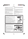
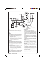
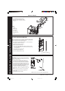
FLUE INSTALLATION
Pluming may occur at the terminal so terminal positions which
would cause a nuisance should be avoided.
The flue must be installed in accordance with the
recommendations of BS. 5440-1:2000. In IE refer to I.S. 813:2002.
The following notes are intended for general guidance:-
1. The boiler MUST be installed so that the terminal is exposed
to external air.
2. It is important that the position of the terminal allows the free
passage of air across it at all times.
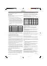
3. Minimum acceptable spacing from the terminal to obstructions
and ventilation openings are specified in Table 3.
4. Where the lowest part of the terminal is fitted less than 2m
(6'6") above a balcony, above ground or above a flat roof to
which people have access then the terminal MUST be protected
by a purpose designed guard.
Terminals guards are available from boiler suppliers - ask for
TFC Flue Guard, Model No. K6-round, plastic coated. In case of
difficulty seek advice from:
Grasslin (UK) Ltd., Tower House, Vale Rise, Tonbridge,
Kent TN9 1TB.
Tel: +44 (0) 1732 359 888. Fax: +44 (0) 1732 354 445
www.tfc-group.co.uk
Ensure that the guard is fitted centrally.
5. The flue assembly shall be so placed or shielded as to prevent
ignition or damage to any part of any building.
6. The air inlet/products outlet duct and the terminal of the boiler
MUST NOT be closer than 25mm (1") to combustible material.
Detailed recommendations on the protection of combustible
material are given in BS.5440-1:2000. In IE refer to I.S. 813:2002.
IMPORTANT. It is absolutely ESSENTIAL to ensure, in practice, that
products of combustion discharging from the terminal cannot re-
enter the building or any other adjacent building through ventilators,
windows, doors, other sources of natural air infiltration, or forced
ventilation/air conditioning.
If this should occur, the appliance MUST be turned OFF, labelled
'unsafe' and corrective action taken.
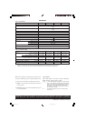
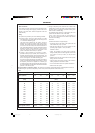
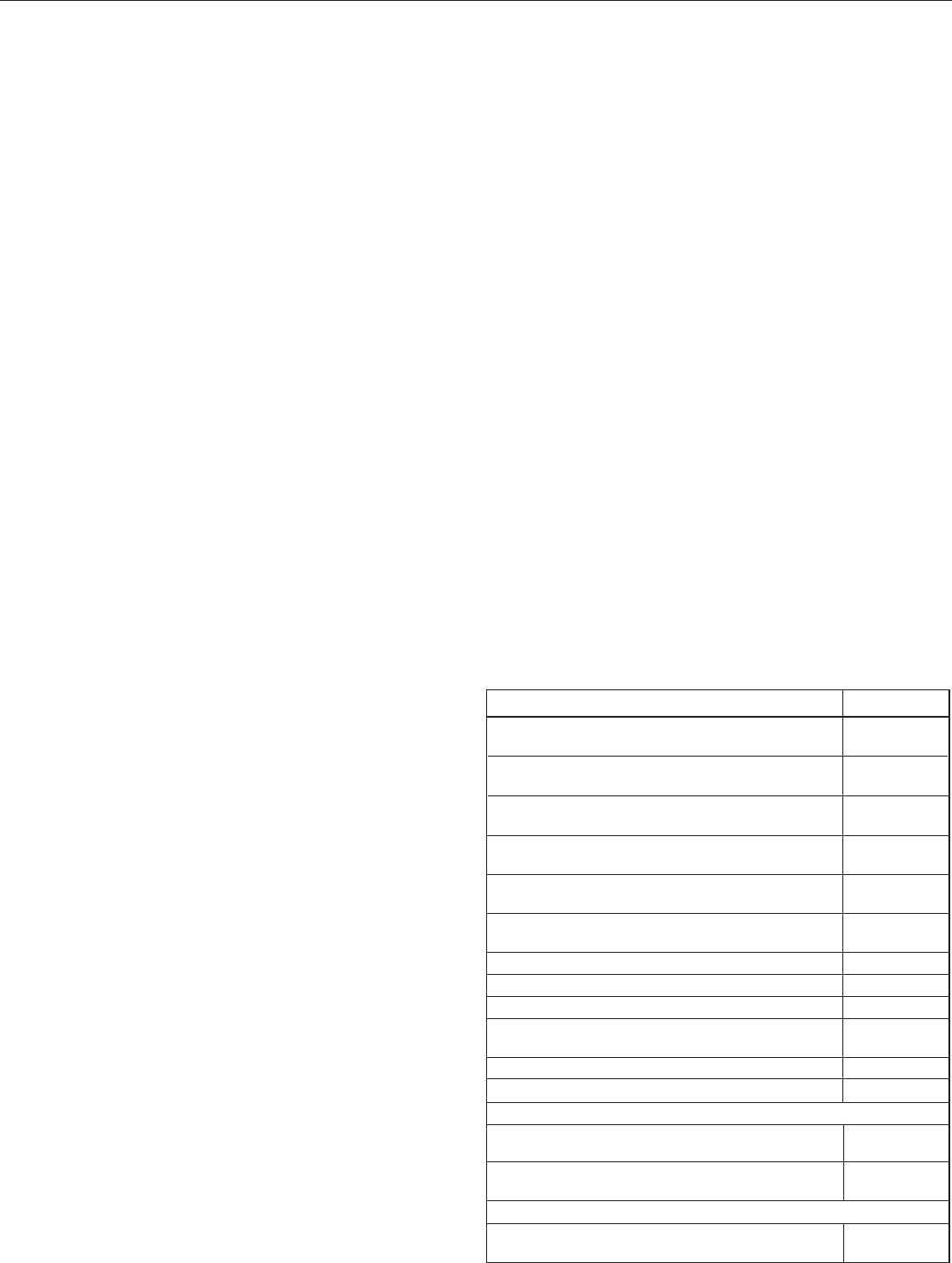
Flue Terminal Positions
Min. Spacing*
1. Directly below or alongside an opening
window, air vent or other ventilation opening. 300mm (12")
2. Below guttering, drain pipes or soil pipes. 25mm ( 1")*
BS5440-1 2000 75mm (3")
3. Below eaves. 25mm (1")*
BS5440-1 2000 200mm (8")
4. Below balconies or a car port roof. 25mm (1")*
BS5440-1 2000 200mm (8")
5. From vertical drain pipes or soil pipes. 25mm (1")*
BS5440-1 2000 150mm (6")
6. From an internal or external corner or to a 25mm (1")*
boundary along side the terminal. BS5440-1 2000 300mm (12")
7. Above adjacent ground, roof or balcony level. 300mm (12")
8. From a surface or a boundary facing the terminal. 600mm (24")
9. From a terminal facing a terminal. 1,200mm (48")
10. From an opening in a car port
(e.g. door or window) into dwelling. 1,200mm (48")
11. Vertically from a terminal on the same wall. 1,500mm (60")
12. Horizontally from a terminal on the wall. 300mm (12")
Vertical Terminals
13. Above the roof pitch with roof slope of all angles. 300mm (12")
Above flat roof. 300mm (12")
14. From a single wall face. 600mm (24")
From corner walls. 1000mm (40")
Twin Flue Applications
15. Centre distance between air inlet and flue
outlet ducts. 120mm (5")
Table 3 - Balanced Flue Terminal Position
* Only one reduction down to 25mm is allowable per installation
otherwise BS5440-1 2000 dimensions must be followed.
201850-6.pmd 21/02/2008, 12:578