


30
classic HE - Installation & Servicing
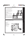
INSTALLATION
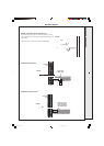
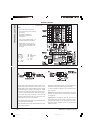
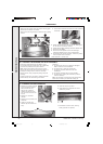
Notes.
1. Some earth wires are omitted for
clarity. Ensure proper earth continuity
when wiring.
2. Numbering of terminals on
thermostats is specific to the
manufacturer.
3. This is a fully controlled system - set
the boiler thermostat to maximum.
4. Switchmaster valve has grey and
orange auxiliary switch leads but the
grey wire must be connected to the
live supply.
45
TWO SPRING CLOSED VALVE
Pumped only
gy grey
y/g yellow/green
or orange
v violet
pk pink
LEGEND
b blue
bk black
br brown
r red
y yellow
w white
46
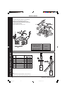
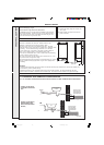
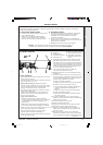
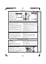
FROST PROTECTION
Central heating systems fitted wholly inside the house do not
normally require frost protection as the house acts as a
'storage heater' and can normally be left at least 24 hrs. without
frost damage. However, if parts of the pipework run outside
the house or if the boiler will be left off for more than a day or
so, then a frost thermostat should be wired into the system.
This is usually done at the programmer, in which case the
programme selector switches are set to OFF and all other
controls MUST be left in the running position.
The frost thermostat should be sited in a cold place but where
it can sense heat from the system.
Wiring should be as shown, with minimal disturbance to other
wiring of the programmer.
Designation of the terminals will vary but the programmer and
thermostat manufacturer's leaflets will give full details.
If a boiler is installed in a garage it may be necessary to fit a
pipe thermostat.
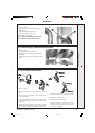
Diagram A shows a double pole frost thermostat, which should
suffice for all systems which do not use the OFF terminals of
the programmer.
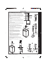
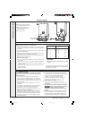
Diagram B shows a 'change-over' frost 'stat', which will cover
most systems which do use CH OFF. If, however, on such a
system the HW pipework is in an isolated part of the house, a
second frost 'stat may be used to protect it. If in doubt, ask your
installer for advice.
INSTALLATION
201850-6.pmd 21/02/2008, 12:5830