


classic HE - Installation & Servicing
31
INSTALLATION
47
COMMISSIONING AND TESTING
A. ELECTRICAL INSTALLATION
1. Checks to ensure electrical safety should be carried
out by a competent person.
2. ALWAYS carry out preliminary electrical system
checks, i.e. earth continuity, polarity, resistance to
earth and short circuit using a suitable test meter.
WARNING. Whilst effecting the required gas soundness test and purging air from the gas
installation open all windows and doors, extinguish naked lights and DO NOT SMOKE.
B. GAS INSTALLATION
1. The whole of the gas installation, including the meter, MUST
be inspected and tested for soundness, and purged in
accordance with the recommendations of BS. 6891.
In IE refer to I.S.813:2002.
2. Purging air from the gas installation may be expedited by
loosening the union on the gas service cock on the boiler and
purging until gas is detected.
3. Retighten the union and check for gas soundness.
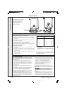
TO LIGHT THE BOILER
1. Check that all the drain cocks are closed, and any valves in
the flow and return are open.
2. Check that the gas service cock (B) is OPEN and the boiler
mains On/Off switch (H) is OFF.
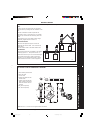
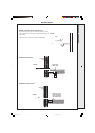
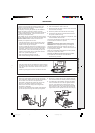
3. Fitting the Boiler Casing (See diagram A, Frame 49)
Hook the top edge of the boiler front casing into the channel
on the top of the boiler assembly. Swing the bottom of the
casing down and secure with the 2 captive screws.
The casing must seat correctly and compress the sealing
strip to make an airtight joint.
Visually check the side seals but, if side clearances are
limited, then check that the top and bottom edges of the
casing are correctly located.
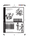
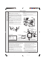
To gain access to the gas valve:
a. Remove the controls support casing. Release the
controls support front fixing screws 3 turns only. Remove
the pod by pulling it forward to disengage from the
keyhole slots.
b. Remove the control box securing screws and swing it
down into the servicing position. (See diagram B, Frame 49) .
4. Slacken the screw in the burner pressure test point (F) and
connect a gas pressure gauge via a flexible tube.
5. Swing the control box back into its working position.
6. Press the overheat thermostat reset button (J).
7. Switch the electricity supply ON and check that all external
controls are calling for heat.
48
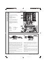
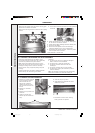
INITIAL LIGHTING
8. Set the boiler thermostat knob (D) to position 6 and the
boiler Mains On/Off switch (H) to ON. The fan will start.
After the fan has run for a few seconds the pilot solenoid
valve should open and the intermittent spark commence,
continuing until the pilot is established. The main burner
will then cross-light smoothly. If this sequence does not
occur, refer to the Fault Finding section.
9. Test for gas soundness around ALL boiler gas
components using leak detection fluid.
10.Operate the boiler for 10 minutes to stabilise the burner
temperature.
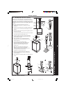
11. The boiler is pre-set at the factory to its nominal rating. If
the burner pressure measured is incorrect it may be reset
using the following procedure. Refer to Table 2 (page 4):
a. Set the mains On/Off switch (H) to OFF.
b. Switch the electricity supply OFF.
c. Swing the control box down into the servicing position.
d. Remove the main burner adjuster cover (E).
e. Turn the adjusting screw clockwise to INCREASE the
pressure, or anticlockwise to DECREASE the
pressure.
f. Swing the control box back into its working position.
g. Switch the electricity supply ON.
h. Set the mains On/Off switch (H) to ON and check the
new setting pressure.
12.If necessary repeat steps 11a to h until the required
pressure is achieved. Record this value in the Benchmark
Commissioning Checklist.
13.Set the main On/Off (H) switch to OFF.
14.Switch the electricity supply OFF.
15.Swing the control box down into the servicing position.
16.Refit the main burner pressure adjuster cover.
17.Remove the pressure gauge and tube. Retighten the
sealing screw in the pressure test point. Ensure a gas
tight seal is made.
18.After the gas pressure checks and any adjustment
operations, the adjustment screw cover must be sealed
with a suitable paint to highlight unauthorised adjustment.
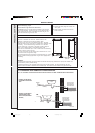
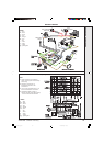
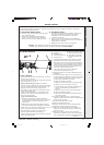
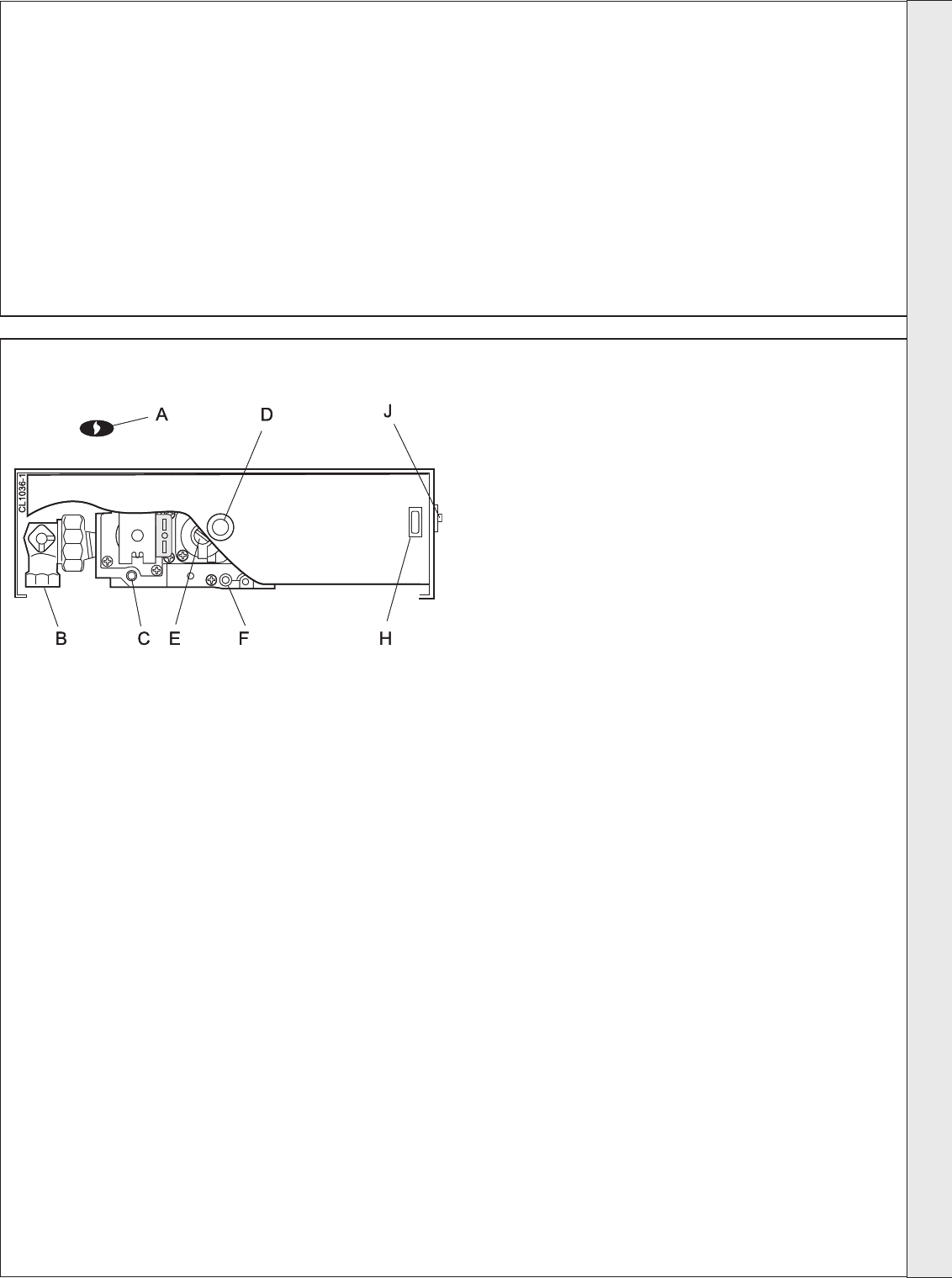
LEGEND
A Sightglass.
B Gas service cock.
C Inlet pressure test point.
D Thermostat knob
E Main burner pressure adjuster.
F Burner pressure test point.
H Boiler mains on/off switch.
J Overheat thermostat reset
button.
The Benchmark Log Section of this book or equivalent self certification should be completed and signed to demonstrate
compliance with Building Regulations.
continued . . . . . . . . .
INSTALLATION
201850-6.pmd 21/02/2008, 12:5831