


classic HE - Installation & Servicing
35
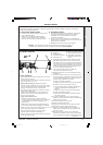
SERVICING
MAIN BURNER
After any servicing, reference should be made to Table 2
which quotes details of the rated output with the related
burner setting pressure and the heat input. Any required
adjustments should be made by using the pressure
adjustment screw.
Refer to 'initial Lighting', Frame 48.
REPLACEMENT OF PARTS
61
GENERAL
When replacing any component:
1. Isolate the electricity supply.
2. Turn OFF the gas supply.
3. Remove the boiler front panel. Refer to Frame 53.
IMPORTANT. When work is complete the casing must be
correctly refitted, ensuring that a good seal is made.
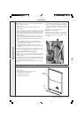
60
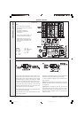
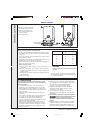
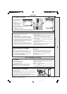
GAS PRESSURE ADJUSTMENT
cla7151
PILOT
The pilot is factory set to maximum and no further
adjustment is possible. If, after removing and checking the
injector (as detailed in Frame 67) and ensuring that there
is an inlet pressure of 20 mbar available, the pilot does not
light then contact Ideal Stelrad Group.
Relight in accordance with 'Initial Lighting', Frame 48.
Note. In order to assist fault finding, the control box printed
circuit board is fitted with 2 indicator lights which represent the
following boiler conditions:
Neon I3. Mains electricity ON.
Neon SG1. Flashes to indicate ignition operation (stops after
detection).
The boiler MUST NOT be operated if the casing is not fitted.
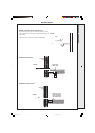
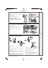
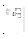
1. Refer to Frame 61.
2. Unfasten the 2 nuts and washers holding the sightglass assembly to
the casing front panel.
3. When fixing the new assembly ensure that the parts are in the correct
order. The frame must have the return edge at the bottom.
4. Retighten the 2 nuts to ensure an airtight seal. Do NOT overtighten.
5. Replace the boiler front panel. Refer to Frame 49 .
59
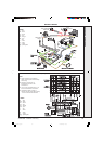
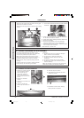
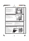
REASSEMBLY
62
SIGHTGLASS REPLACEMENT
58
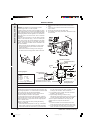
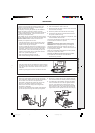
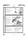
CLEANING THE SIPHON
1. Pull the heat shield forward
to remove from clips.
2. Unscrew the siphon union
connection.
3. Remove the rubber sump
connection pipe and the
blockage sensing pipe.
4. Remove the two siphon
retaining screws and remove siphon.
5. Thoroughly clean the siphon.
6. Recharge the siphon with water.
7. Re-assemble in reverse order. Ensuring the rubber sump
connection pipe and blockage sensing pipe are correctly replaced.
Reassemble the boiler in the following order.
1. Refit the flue baffles.
2. Inspect the collector hood rope gasket and replace, if
necessary, ensuring that the self adhesive rope is fitted
centrally on to the lip of the collector hood / fan assembly.
The boiler efficiency will be adversely affected if incorrectly
fitted. Refit the collector hood and retain with the 2 front
and side tie rods. Tighten the nuts and screw. Ensure that
the sealing gasket is compressed.
3. Refit the fan, fan electrical connections, the thermostat
electrical connections, the red pressure sensing pipe, the
blue CO/CO
2 sensing pipe and the two fan fixing screws.
4. Refit the air box assembly and burner. Ensure that the burner
front fixing is refitted.
5. Refit the combustion chamber, (replacing the rope seal if necessary)
ensuring the two rubber sealing grommets are replaced.
6. Reconnect the gas supply and the electrical wiring. Refer to
Frames 36 & 41.
7. Check the sightglass in the boiler casing. Clean or renew as
necessary. Refer to Frame 62.
8. Check for gas soundness. Check the gas service cock and
pressure test point.
9. Refit the boiler casing (refer to Frame 49). Note that it is not
necessary to disturb the controls casing pod.
10.Close the controls pod door.
1
4
2
3
SERVICING
201850-6.pmd 21/02/2008, 12:5835