


18
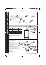
classic HE - Installation & Servicing
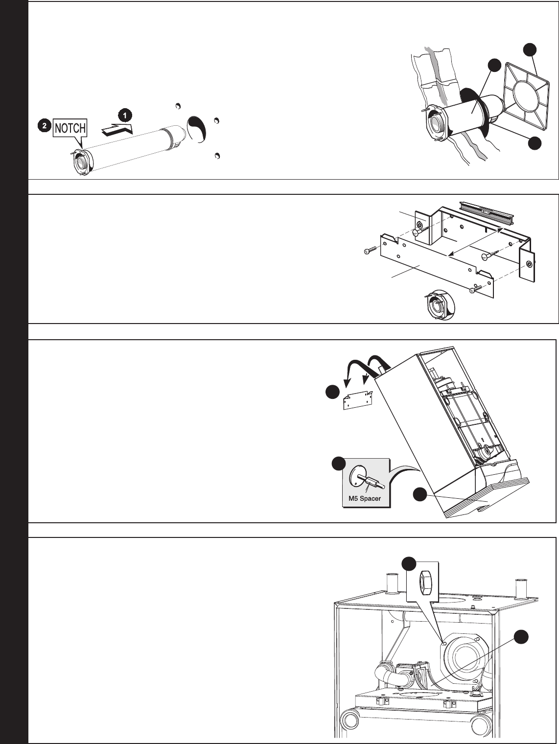
INSTALLATION
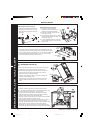
REAR FLUE OUTLET
1. Locate the 3 sealing ring studs in the holes in the back panel.
Note. The sealing ring studs will locate in the back panel one way only.
This will ensure that the terminal grille is correctly aligned.
2. Secure the flue to the boiler using the three M5 nuts provided.
3. Before fitting the flue turret fill the siphon trap within the boiler by
pouring a cupful of water into the recuperator outlet.
Take care to ensure that the water is only poured into the recuperator
outlet, and does not spill into the boiler casing.
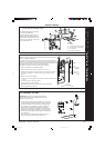
4. Re-engage the recuperator top section flue connecting ring into the
plastic flue pipe and retain the top section with the two screws
previously removed (ensure the top section to main recuperator body
sealing gasket is correctly positioned in its retaining groove).
5. Refit the fan, fan electrical connections, the red pressure sensing
pipe and the blue CO/CO
2 sensing pipe. Refit the 2 fan fixing screws.
18
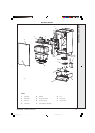
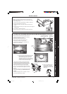
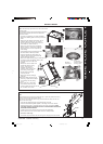
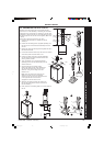
MOUNTING THE BOILER
Note.
The boiler may require two men to lift it onto the wall mounting plate.
For downward routing of pipes the M5 spacer (supplied in the
downward piping kit) should now be fitted to the back of the boiler.
1. Lift the boiler onto the wall mounting plate hooks as shown.
2. Remove the bottom packaging protection.
3. Check the boiler alignment, using a spirit level, and adjust as
necessary with the jacking screw.
4. Line up the hole in the jacking screw with the hole in the wall
previously drilled and secure with the No. 14 x 50mm wood
screw.
19
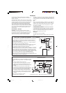
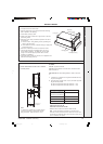
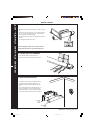
CONNECTING THE FLUE TO THE BOILER
(A) Without Optional Flue finishing Kit
1. Insert the flue assembly through the hole.
2. Ensure the notch is at the top. This will
aid the location of the studs into the boiler
back panel.
cla7640
A
16
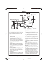
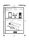
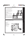
FITTING THE FLUE ASSEMBLY AND OPTIONAL FLUE FINISHING KIT (if required)
cla7663
B
1
4
2
(B) With Optional Flue finishing Kit
1. Fit the black outer wall seal over
terminal and ensure the retaining rim is
located in the terminal depression.
2. Fit flue pipe assembly through the hole
previously cut in wall.
3. Fit wall mounting plate (Frame 17), mount
the boiler (Frame 18) and connect the flue
to the boiler (frame 19).
4. Fit outer wall sealing plate over outer wall
seal and retain with the 4 screws and wall
plugs provided.
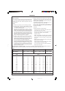
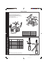
17
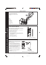
WALL MOUNTING PLATE
cla8181
Downward
piping
bracket
Wall mounting
bracket
36mm
Jacking screw
cla7664
1
3
2
cla7665
3
2
1. If downward routing of pipes is required then the downward routing wall
bracket supplied in the downward piping kit should be fitted to the wall now.
2. Fix the mounting plate to the wall with the No. 14 x 50mm wood screws or to
the downward piping bracket with the M6 x 12 Hex hd screws provided.
3. Check with a spirit level that the plate is horizontal.
201850-6.pmd 21/02/2008, 12:5818