


28
classic HE - Installation & Servicing
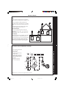
INSTALLATION
cla7738
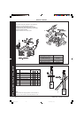
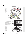
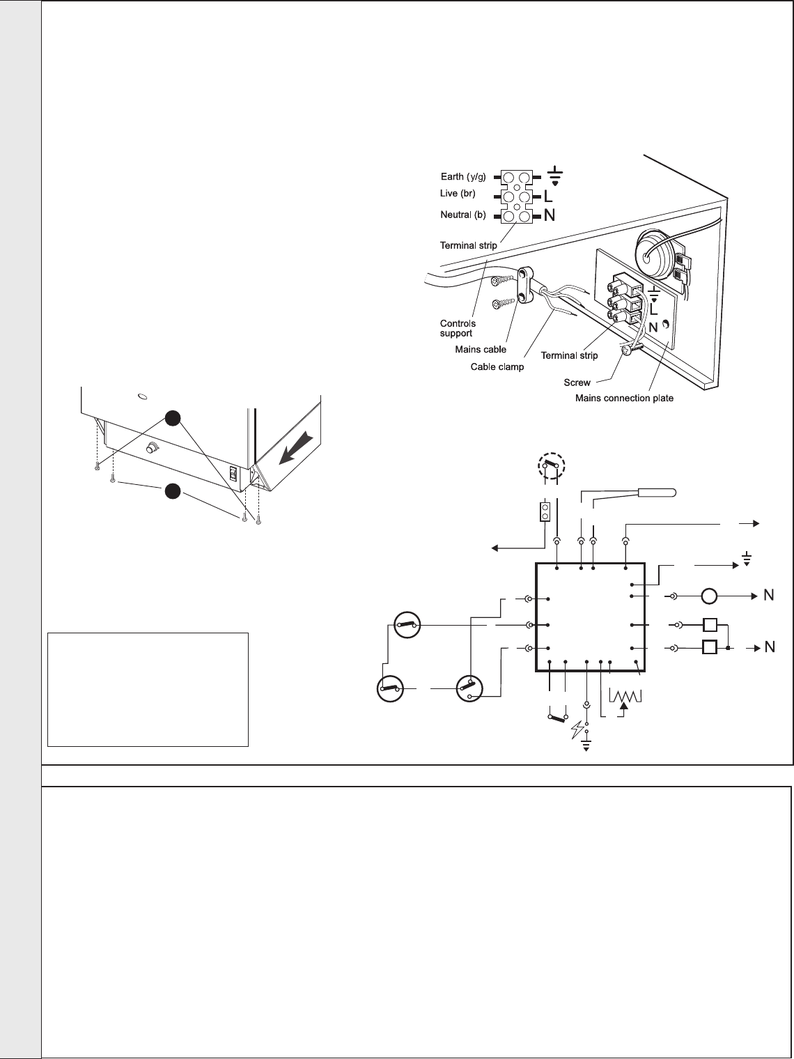
Limit
thermostat
O/heat thermostat
Thermostat sensor
L
br
br
L
On/Off switch
ALL EARTHS must be connected
(Not all earths are shown for clarity)
Air pressure
switch
Flue protection
thermostat
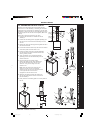
cla7856
Combined spark &
sensing electrode
Potentiometer
L
NTC
NC
N
C
NO
P.C.B. 25
GV 1
GV 2
FAN
E
Main gas
Pilot gas
Fan
b
b
Connect
to
gy
bk
br
or
pk
w
y/g
N
bk
bk
NO
NC
com
bk
bk
r
r
y
v
41
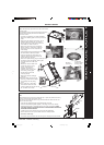
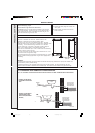
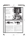
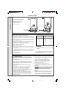
ELECTRICAL CONNECTIONS
External wiring must be in accordance with the current I.E.E. (BS
7671) Wiring Regulations. For Ireland reference should be made
to the current ETCI rules for electrical installations.
The wiring diagrams illustrated in Frames 43-46 cover the
systems most likely to be fitted to this appliance.
For wiring external controls to the classic HE boiler, reference
should be made to the system wiring diagrams supplied by the
relevant manufacturer, in conjunction with the wiring diagrams
shown in Frames 43-46.
Difficulty in wiring should not arise, providing the following
directions are observed:
1. Controls that switch the system on or off, e.g. a time switch,
must be wired, in series, in the live mains lead to the boiler.
2. Controls that override an on/off control, e.g. frost thermostat,
must be wired into the mains lead, in parallel, with the
control(s) to be overridden. Refer to Frame 46.
3. If a proprietary system is used, follow the instructions
supplied by the manufacturer.
4. System designs featuring controls or wiring
arrangements which allow the boiler to fire when there is
no pump circulation taking place should not be fitted.
Advice on required modifications to the wiring may be
obtained from the component manufacturers.
Notes.
1. Connection between a frost thermostat and the time
control should be made without disturbing other wiring.
2. A frost thermostat should be sited in a cool place in the
house, but where it can sense heat from the system.
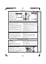
LEGEND
b blue
bk black
br brown
gy grey
or orange
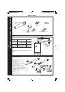
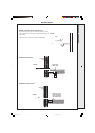
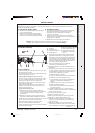
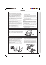
42
EXTERNAL CONTROLS
WARNING. The appliance must be efficiently earthed.
A mains supply of 230 V ~ 50 Hz is required.
All external controls and wiring must be suitable for mains
voltage. Wiring should be in 3-core PVC insulated & sheathed
cable, not less than 0.75mm
2
(24 x 0.2mm) to BS. 6500 Table
16 Wiring Regulations and local regulations. For IE reference
should be made to the current ETCI rules for electrical
installations.
Connection must be made in a way that allows complete
isolation of the electrical supply - such as a double pole
switch, having a 3mm (1/8") contact separation in both poles
or a plug and socket, serving only the boiler and system
controls. The means of isolation must be accessible to the
user after installation.
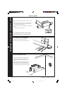
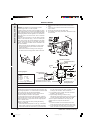
1. Remove controls pod by slackening front fixing screws
and pull pod forward (may find it easier to remove the
controls pod door).
2. Remove the control box securing screws. Swing the
box down into the servicing position. Refer to Frame 49.
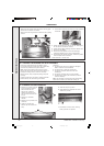
Flow wiring diagram
pk pink
r red
v violet
w white
y/g yellow/green
cla7923
2
1
3. Route the mains cable into the box from the RHS of the
boiler.
4. Connect the live, neutral and earth wires into the terminal
strip as shown.
5. Secure the mains lead with the cable clamp.
6. On completion of all wiring connections, relocate the control
box and secure.
INSTALLATION
201850-6.pmd 21/02/2008, 12:5828