


10
classic HE - Installation & Servicing
GENERAL
Minimum Requirements
Note. The pump manufacturers minimum
requirements must be complied with.
System
return
Connections
to boiler
Inverted cold
feed entry
System
flow to
pump
150 (6")
Max
15mm
Cold
feed
450 (17
3
/
4
")
Mimimum
450 (17
3
/
4
")
Mimimum
22mm
Open vent
Feed / expansion
cistern
Water
level
(cold)
cla7840
Surge
arrester
75 (3)
Min.
450
(17
3
/
4
")
Min.
200
(8)
Min.
Highest
point of
flow or
return
150
(6)
Max
Max. practical
length
To pump
Cold
water
level
Feed / expansion
cistern
75 (3) Min.
Flow
Return
22 (3/4)
Open vent
cla7839
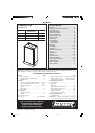
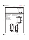
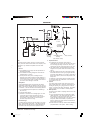
All dimensions in mm (in.). N.B. Imperial dimensions are approximate
4
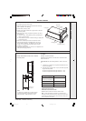
LOW HEAD INSTALLATIONS
The system should be vented directly off the boiler flow pipe, as close to the
boiler as possible. The cold feed entry should be inverted and MUST be
positioned between the pump and the vent, and not more than 150mm (6")
away from the vent connection.
There should be a minimum height - 450mm (17
3
/4") - of open vent above
cistern water level. If this is impossible refer below.
The vertical distance between the highest point of the system and the feed/
expansion cistern water level MUST not be less than 450mm (17
3
/4").
The pump MUST be fitted on the flow side of the boiler.
A suitable pump is a domestic circulator capable of providing an 11
o
C (20
o
F)
temperature differential (e.g. Grundfos UPS 15/50 or equivalent). The vertical
distance between the pump and feed/expansion cistern MUST comply with
the pump manufacturers minimum requirements to avoid cavitation. Should
these conditions not apply, either lower the pump position or raise the cistern
above the minimum requirement specified by Ideal Stelrad Group.
Note. A cold water feed must be available back to the boiler, when all
automatic valves are in the closed position (refer to BS. 6798) and when close
coupled the feed must not be in a vertical leg.
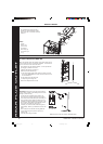
The classic HE range of boilers can be installed in low head
situations by fitting a 'surge arrester' in the expansion pipe as
shown.
The following conditions MUST be observed:
1. The surge arrester must be at least 42mm in diameter x
150mm long, thus ensuring a MINIMUM air gap and a
MINIMUM depth of water below the static water level (cold)
of 75mm.
2. The static water level (cold) must be at least 200mm
above the top of the horizontal flow pipe, fitted as shown.
The vent connection MUST NOT be made immediately off
the top of the boiler, as venting is made less efficient.
3. The maximum practical length of 15mm cold feed pipe
should be used in order to reduce the effective volume of
system water expanding into the feed/expansion cistern to
a minimum.
3
OPEN VENT SYSTEM REQUIREMENTS - FULLY PUMPED
Central heating systems controls should be installed to
ensure the boiler is switched off when there is no demand for
heating or hot water.
When thermostatic radiator valves are used, the space heating
temperature control over a living / dining area or hallway having
a heating requirement of at least 10% of the boiler heat output
should be achieved using a room thermostat, whilst other
rooms are individually controlled by thermostatic radiator
valves. However, if the system employs thermostatic radiator
valves on all radiators, or two port valves without end switches,
then a bypass circuit must be fitted with an automatic bypass
valve to ensure a flow of water should all valves be in the
closed position.
ELECTRICAL SUPPLY
WARNING. The appliance MUST be efficiently earthed.
Wiring external to the appliance MUST be in accordance with
the current I.E.E. (BS.7671) Wiring Regulations and any local
regulations which apply. For Ireland reference should be
made to the current ETCI rules for electrical installations.
The point of connection to the mains should be readily accessible
and adjacent to the boiler, except that for bathroom installations; the
point of connection to the mains MUST be situated outside of the
bathroom.
Note.
Where a room sealed appliance is installed in a room containing
a bath or shower then the appliance and any electrical switch or
appliance control utilising mains electricity should be so situated
that it cannot be touched by a person using the bath or shower.
See Frame 41 for details.
CONDENSATE DRAIN Refer to Frames 38, 39 and 40
A condensate drain siphon is provided on the boiler. This drain
must be connected to a drainage point on site. All pipework and
fittings in the condensate drainage system MUST be made of
plastic- no other materials may be used.
IMPORTANT.
Any external runs must be insulated.
The drain outlet on the boiler is standard 21.5mm (3/4") overflow
pipe.
201850-6.pmd 21/02/2008, 12:5710