


16
classic HE - Installation & Servicing
INSTALLATION
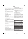
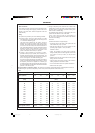
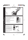
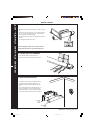
REAR FLUE OUTLET
1
2
3
4
5
6
Note. Check all of the hole positions BEFORE drilling
11
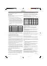
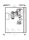
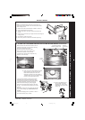
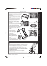
FLUE ASSEMBLY - Exploded View
LEGEND
1. Terminal
2. Weather seal
(optional extra)
3. Flue assembly
4. Boiler sealing ring
5. Flue extension pipe
6. 'O' ring
1. An optional flue duct extension kit is
required for wall thicknesses greater
than 775mm (30
1
/2") side flue. Refer to
Frame 10.
12
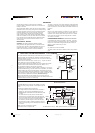
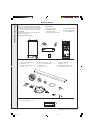
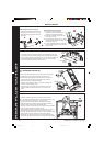
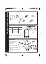
WALL MOUNTING TEMPLATE
Note. The template shows the positions of the fixing holes and the
rear flue outlet hole centre for standard installation. Care MUST be
taken to ensure the correct holes are drilled.
1. Tape template into the selected position. Ensure squareness
by hanging a plumbline as shown.
2. If fitting a side flue refer to Frame 21.
3. Mark onto the wall the following:
a. The wall mounting plate screw positions (choose one from
each group). Note. Mark the centre of the flue hole as well as
the circumference.
b. The position of the flue duct hole.
c. The jacking screw fixing hole.
4. Remove the template from the wall.
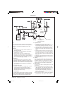
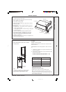
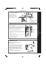
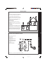
IMPORTANT. Ensure that, during the cutting operation,
masonry falling outside of the building does not cause
damage or personal injury.
1. Cut the flue hole, preferably with a 125mm (5")
core boring tool, ensuring that the hole is square
to the wall. If the hole has been quite accurately cut
with a drill then making good the wall faces is not
essential as seals are provided at both ends of the
flue. However, both wall faces immediately around
the cut hole should be flat; make good if
necessary. For less accurate holes make good to
approximately 125mm (5") diameter at the two wall
faces.
2. Drill 3 holes (two for the wall mounting plate and
one for the jacking screw) with an 8mm (
5/16")
masonry drill.
3. Insert the plastic plugs provided.
13
PREPARING THE WALL
cla7661
201850-6.pmd 21/02/2008, 12:5816