


classic HE - Installation & Servicing
33
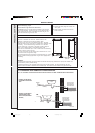
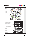
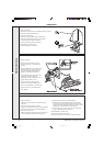
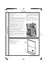
SERVICING
cla7851
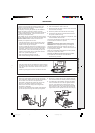
2 casing
retaining
screws
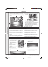
To ensure the continued safe and efficient operation of the
appliance it is recommended that it is checked at regular
intervals and serviced as necessary.
The frequency of servicing will depend upon the installation
condition and usage, but should be carried out at least
annually. It is the law that any service work must be carried out
by CORGI registered installer. In IE service work must be
carried out by a Competent Person.
As the installer you may wish to undertake the service contract
yourself or alternatively offer to the customer the benefits of the
Ideal Care Scheme, details of which are outlined in the
household pack supplied with this boiler.
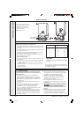
1. Light the boiler and carry out a pre-service check, noting
any operational faults. Operate the boiler for at least 20
minutes. Check the gas consumption.
2. Connect a suitable gas analyser to the sampling point on
the top RHS of the back panel. For correct boiler operation
the CO/CO
2
content of the flue gas should not be greater
than 0.004 ratio. If this is the case and the gas input is at
least 90% of the nominal, then no further action need be
taken. If not, proceed to paragraph 3.
3. Clean the main burner. Refer to Frame 56.
4. Clean the heat exchanger. Refer to Frame 55.
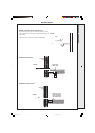
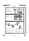
1
3
2
4
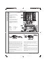
cla9214
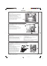
4. Remove the 4 screws retaining the air box/pilot assembly
to the vertical manifold and carefully remove the assembly.
5. On re-fitting the air box assembly, remove the old gasket
from the manifold and ensure the new gasket is located
correctly. Check that the joint is made gas tight. Ideal
Boilers recommend the air box fixing screws be replaced
with a torque of 4.0Nm in the number order shown on the
diagram below and be repeated to ensure even clamping.
54
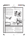
BURNER AND AIR BOX REMOVAL
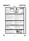
1. Remove the screw retaining the front burner support strap
to the combustion chamber. Remove the M5 pozi situated at
the LH bottom rear of the burner and pull the burner
downwards to disengage the retention tab. Remove the
burner to a safe place for inspection and cleaning.
2. Remove the 2 control box fixing screws. Swing the box
downwards to disengage.
3. Pull the HT lead connection off the printed circuit board and
pull the lead upwards through the bottom panel grommet.
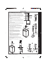
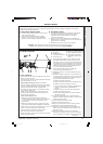
1. Open the controls pod door and release the 2 captive screws at
the bottom of the casing, then unhook the casing front panel
from the back panel and remove. Retain the front panel in a
safe place.
2. Isolate the gas supply at the service cock fitted to the boiler.
53
BOILER FRONT PANEL REMOVAL
52
SERVICING SCHEDULE
5. Clean the main and pilot injectors. Refer to Frame 56.
6 Clean the recuperator. Refer to Frame 57.
7. Remove and clean the siphon. Refer to Frame 58 and then
check the drain for blockage.
8. Remove any debris from inside the base of the casing.
9. Check that the flue terminal is unobstructed and that the
flue system is sealed correctly.
10.If the appliance has been installed in a compartment, check
that the ventilation areas are clear.
The servicing procedures are covered more fully in Frames 54
to 60 and must be carried out in sequence.
WARNING
.
Disconnect the electrical supply and turn off gas supply.
IMPORTANT. After completing the servicing or exchange of
components always test for gas soundness and carry out
functional checks as appropriate. Refer to Frame 48, item 18
for gas adjustment sealing.
When work is complete the casing MUST be correctly refitted,
ensuring that a good seal is made.
T
he boiler must NOT be operated if the casing is not fitted.
11. Complete the service section of the Benchmark
Commissioning Checklist.
SERVICING
201850-6.pmd 21/02/2008, 12:5833