


12
classic HE - Installation & Servicing
GENERAL
6
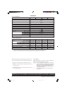
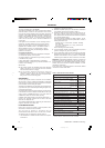
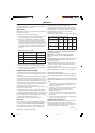
SEALED SYSTEM REQUIREMENTS - continued
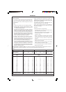
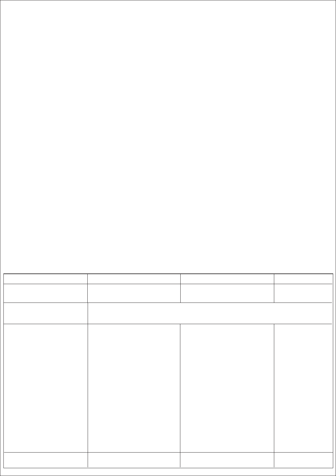
Sizing procedure for expansion vessels: The volume of the expansion vessel (litres) fitted to a sealed system shall not be
less than that given by Table 6, multiplied by a factor of 0.8 (for flow temperatures of less than 88
o
C).
Safety valve setting 3.0 bar 2.5 bar 2.0 bar
Vessel charge and initial 0.5 1.0 1.5 0.5 1.0 1.5 0.5 1.0
system pressure bar bar bar bar bar bar bar bar
Total water content of system Expansion vessel volume
(litres) (litres)
25 2.1 2.7 3.9 2.3 3.3 5.9 2.8 5.0
50 4.2 5.4 7.8 4.7 6.7 11.8 5.6 10.0
75 6.3 8.2 11.7 7.0 10.0 17.7 8.4 15.0
100 8.3 10.9 15.6 9.4 13.4 23.7 11.3 20.0
125 10.4 13.6 19.5 11.7 16.7 29.6 14.1 25.0
150 12.5 16.3 23.4 14.1 20.1 35.5 16.9 30.0
175 14.6 19.1 27.3 16.4 23.4 41.4 19.7 35.0
200 16.7 21.8 31.2 18.8 26.8 47.4 22.6 40.0
225 18.7 24.5 35.1 21.1 30.1 53.3 25.4 45.0
250 20.8 27.2 39.0 23.5 33.5 59.2 28.2 50.0
275 22.9 30.0 42.9 25.8 36.8 65.1 31.0 55.0
300 25.0 32.7 46.8 28.2 40.2 71.1 33.9 60.0
Multiplying factors for
other system volumes 0.0833 0.109 0.156 0.094 0.134 0.237 0.113 0.20
7. Mains Connection
There must be no direct connection to the mains water supply
or to the water storage tank supplying domestic water, even
through a non-return valve, without the approval of the local
water authority.
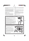
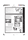
8. Filling
The system may be filled by one of the following methods:
a. Through a cistern, used for no other purposes, via a ball
valve permanently connected directly to a service pipe and
/ or a cold water distributing pipe.
The static head available from the cistern should be
adequate to provide the desired initial system design
pressure. The cold feed pipe from the cistern should include
a non-return valve and a stop valve with an automatic air
vent connected between them, the stop valve being located
between the system and the automatic air vent. The stop
valve may remain open during normal operation of the
system if automatic water make-up is required.
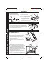
b. Through a self-contained unit comprising a cistern,
pressure booster pump (if required) and, if necessary, an
automatic pressure reducing valve and flow restrictor. The
cistern should be supplied through a temporary connection
from a service pipe or cold water distributing pipe.
This unit may remain permanently connected to the heating
system to provide limited automatic water make-up. Where
the temporary connection is supplied from a service pipe
or distributing pipe which also supplies other draw-off points
at a lower level then a double check valve shall be installed
upstream of the draw-off point.
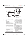
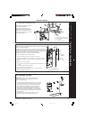
c. Through a temporary hose connection from a draw-off tap
supplied from a service pipe under mains pressure. Where
the mains pressure is excessive a pressure-reducing valve
shall be used to facilitate filling.
The following fittings shall form a permanent part of the
system and shall be fitted in the order stated:
A stop valve complying with the requirements of
BS. 1010, Part 2 (the hose from the draw-off tap shall be
connected to this fitting).
A test cock.
A double check valve of an approved type.
• Thoroughly flush out the whole of the system with cold
water, without the pump in position.
• With the pump fitted, fill and vent the system until the
pressure gauge registers 1.5 bar (21.5lb/in
2
).
Examine for leaks.
• Check the operation of the safety valve by manually
raising the water pressure until the valve lifts. This should
occur within ± 0.3 bar (± 4.3lb/in
2.
) of the pre-set lift
pressure.
• Release water from the system until the initial system
design pressure is reached.
• Light the boiler and heat the system to the maximum
working temperature. Examine for leaks.
• Turn off the boiler and drain the system while still hot.
• Refill and vent the system.
Table 6
201850-6.pmd 21/02/2008, 12:5712