


classic HE - Installation & Servicing
21
INSTALLATION
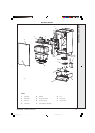
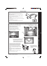
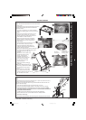
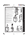
SIDE FLUE OUTLET
cla7672
8
Jacking screw
10
9
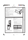
Note. The boiler may require two men to lift it onto the wall
mounting plate.
For downward routing of pipes the M5 spacer (supplied in
the downward piping kit) should now be fitted to the
back of the boiler.
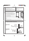
1. The boiler is supplied for rear outlet installation.
Remove the blanking plate from the top outlet and
retain.
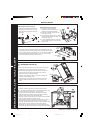
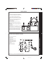
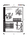
2. Remove the fan electrical connections, the air
pressure switch sensing pipe, the CO/CO
2
sensing pipe and the 2 fan fixing screws and
remove the fan. Refer to frame 15.
3. Remove the top section of the recuperator.
Refer to Frame 15. Remove the rubber fan
seal and fit this to the new recuperator top
outlet casting.
4. Fit the blanking plate and gasket to the rear
flue hole with the 3 M5 nuts provided.
5. Fit the recuperator top outlet casting c/w
rubber fan seal and retain with the two M5
screws previously removed.
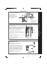
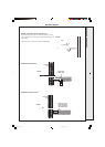
6. Remove the plastic sealing plug and fit the top outlet
connecting casting and gasket, retaining with
the 2 M4 screws and 1 M5 screw
provided.
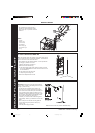
7. Refit the fan into the rubber seal
and secure with the 2 fixing
screws, replace the fan
electrical connections, air
pressure switch sensing pipe
and CO/CO
2
sensing pipe.
8. Lift the boiler onto the wall
mounting bracket.
9. Remove the bottom packaging
protection
10.Check the boiler alignment to the
wall using a spirit level and adjust
as necessary with the jacking
screw.
11. Line up the hole in the jacking
screw with the hole in the wall
previously drilled and secure with the
No. 14x50mm wood screw.
26
MOUNTING THE BOILER
27
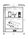
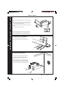
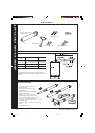
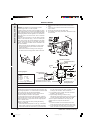
CONNECTING THE FLUE TO THE BOILER
Note.
Before fitting the flue turret fill the condensate trap or siphon trap within the boiler by
pouring a cupful of water into the flue outlet A.
Take care to ensure that the water is only poured into the flue outlet, and does not
spill into the boiler casing.
1. Insert the flue assembly through the prepared hole in the wall.
2. Fit the flat self adhesive gasket supplied, to the flange of the turret, carefully
aligning the fixing holes. Locate the flue turret on the top of the boiler. CHECK
THAT THE FLUE SEAL LOCATED IN THE TOP OF THE FLUE MANIFOLD IS SECURE
AND GIVING AN EFFECTIVE SEAL.
3. Locate the flue into the turret and push to ensure full engagement.
4. Secure the flue turret on top of the boiler with the 4 screws provided.
5. Flues over 1 metre long.
Fix the flue support bracket to the wall, using the 2 wall plugs and wood screws.
2
3
cla8184
1
A
Gasket
4
4
7
Fixing
screws
Rubber
seal
Electrical
connections
Air pressure
switch & CO/CO2
sensing pipes
6
6
1
cla7844
6
5
201850-6.pmd 21/02/2008, 12:5821