


classic HE - Installation & Servicing
7
GENERAL
This appliance in NOT suitable for use in a direct
hot water system or for gravity circulation.
1
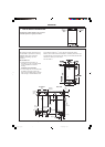
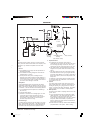
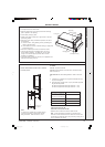
BOILER WATER CONNECTIONS
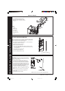
The following minimum clearances must
be maintained for operation and servicing.
Additional space will be required for
installation, depending upon site
conditions.
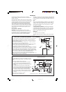
Side and Rear Flue
a. Provided that the flue hole is cut
accurately, e.g. with a core drill, the flue
can be installed from inside the
building.
Installation from inside ONLY
b. If a core boring tool is to be used inside
the building; the space in which the
boiler is to be installed must be at least
wide enough to accommodate the tool.
Front clearance: 450mm (17
3
/4") from the front of the boiler casing.
Minimum front clearance when built behind a concealed panel is 5mm (
1
/4")
provided that the top and bottom of the casing is not enclosed and the side
clearance is 40mm (2") at both sides.
See also Table 4.
2
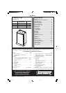
BOILER CLEARANCES
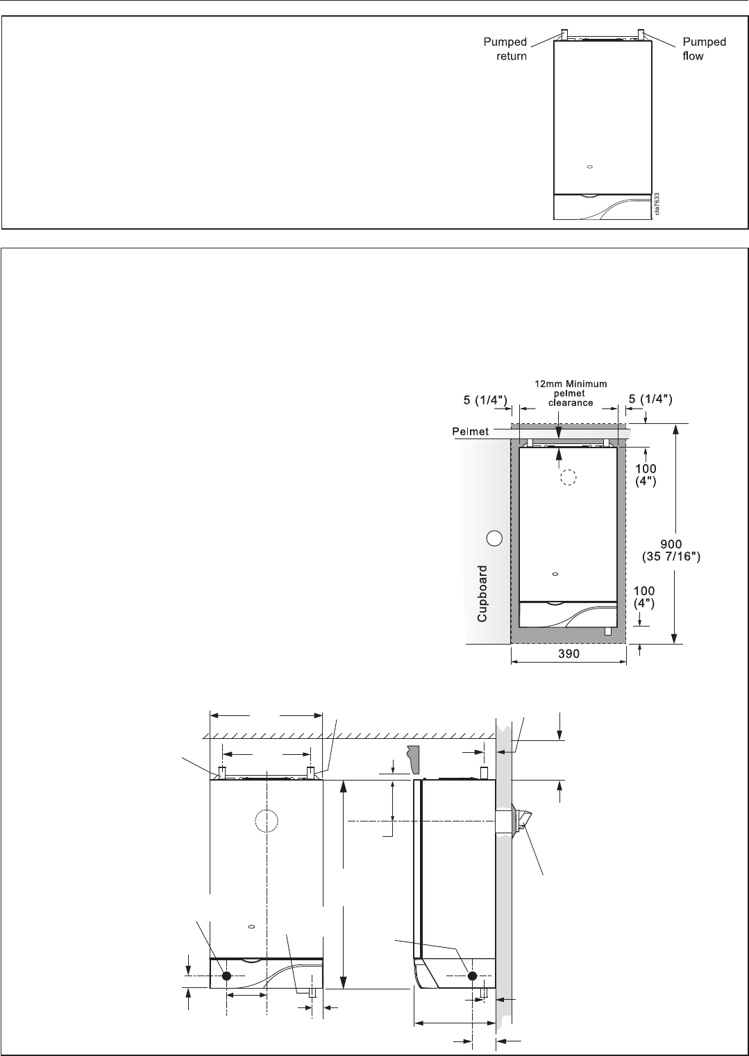
133
(5
1
/4")
380
(15")
296
(11
5
/8")
Pumped
return
pipe
Pumped
flow pipe
12 (
1
/2")
100
(4")
44
(1
3
/4")
Flue
terminal
280 (11")
70 (2
3
/4")
Gas
connection
700
(27
1
/2")
141
(5
9
/16")
cla8230
Front View Side View
64 (2
1
/2")
38 (1
1
/2")
20 (
3
/4")
Gas
connection
Condensate
drain point
cla7635
(15 3/8")
201850-6.pmd 21/02/2008, 12:577