


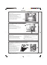
34
classic HE - Installation & Servicing
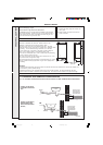
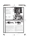
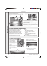
SERVICING
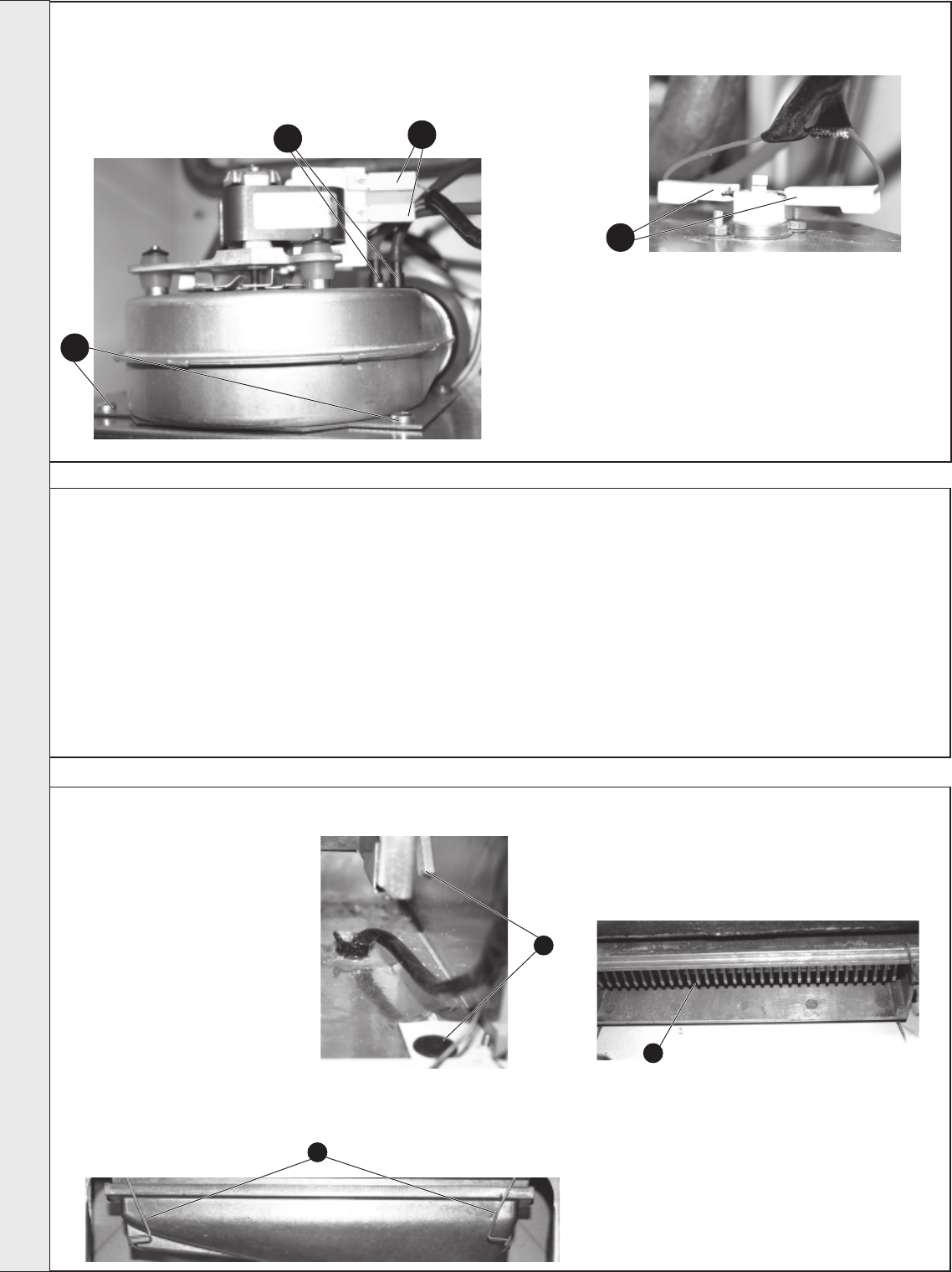
1. Remove the air pressure switch and CO/CO2 sensing pipes.
2. Disconnect the electrical connections.
3. Remove the 2 fan fixing screws and remove the fan by pulling
forward.
55
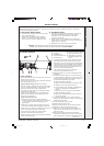
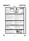
CLEANING THE FAN ASSEMBLY
/
THE FLUEWAYS
56
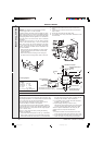
CLEANING THE BURNER AND PILOT ASSEMBLY
1. Brush off any deposits that may have fallen on to the
burner head (ensuring the flame ports are unobstructed)
and remove any debris that may have collected.
Note. Brushes with metallic bristles must not be used.
2. Remove the main burner injector and ensure there is no
blockage or damage. Clean or renew as necessary.
3. Refit the injector, using an approved jointing compound
sparingly.
4. Inspect the pilot burner and ignition / detection electrode.
Ensure that they are clean and in good condition.
Check that:
a. The pilot burner injector is not blocked or damaged.
Refer to Frame 67 for removal details.
b. The pilot burner is clean and unobstructed.
c. The ignition / detection electrode is clean and
undamaged.
d. The ignition / detection lead is in good condition.
e. The spark gap is correct (refer to Frame 67) Clean or
renew as necessary.
Note. The pilot shield is located around the pilot assembly
bracket and is located by the electrode retaining nut.
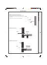
57
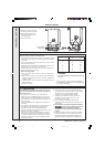
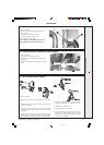
CLEANING THE RECUPERATOR
1. Remove the 2 rubber grommets
to gain screwdriver access to
remove the side tie rods
retaining the combustion
chamber and remove the tie
rods. Also remove the two front
tie rods.
2. Remove the combustion
chamber.
3. Remove the sump rubber hose
connection.
4. Unclip the two side sump
retention clips and remove the
sump.
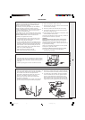
4. Pull off the two electrical connections to the flue protection
thermostat.
5. Clean the sump of any debris.
6. Clean between the recuperator fins with a
suitable strip of steel.
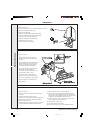
5. Slacken the two M5 nuts on the front tie rods, releasing the
tie rods from the combustion chamber.
6. Unhook the rear collector hood tags and remove collector hood.
7. Remove the flue baffles.
8. Remove all loose deposits from the heat exchanger,
particularly between the fins, using a suitable brush.
9. Check that the fan impellor runs freely. Remove any debris
from the impellor with a soft brush.
10.Re-assemble in reverse order.
7. Re-assemble in reverse order, ensuring
rubber grommets are replaced.
4
3
2
1
1
4
6
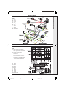
SERVICING
201850-6.pmd 21/02/2008, 12:5834