


Wiring Excel 800
EN1B-0410GE51 R0908A 4
Wiring
All wiring to the XL800 controller is unsupervised, except as
noted.
All circuits are power limited, except for AC power circuits,
relay contacts and other circuits as noted.
All field wiring terminals accept 24 AWG to 14 AWG
(0.25 mm
2
to 2 mm
2
) conductors except as noted.
All wiring must conform to local codes, ordinances, and
regulations. Refer to job drawings for details.
Verify that the voltage difference between any conductor and
earth ground does NOT exceed 150 Vac.
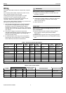
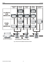
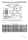
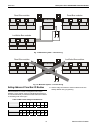
1. Connect input/output device wiring, C-Bus transmission
wiring (minimum 18 gage [0.8012 sq mm]), LON Bus
transmission wiring, and 14507063 Power Cable to
Controller per job drawings. Fig. 2 and Fig. 3 show typical
controller wiring. Four Power Module models are available
(see Table 2).
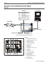
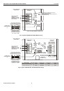
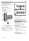
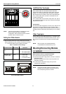
2. Connect line voltage to Terminals H and N of the
14507287 Power Module. Connect a good earth ground to
Terminal G of the Power Module. Fig. 5 through Fig. 7
show typical power wiring.
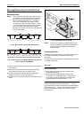
3. For Power Modules -001 through -007, leave power to
Power Supply and Controller OFF. Connect 14507063
Power Cable from Controller to Power Module.
WARNING
Risk of electric shock or equipment damage!
► Subpanel and Controller power must remain OFF until
Controller is checked.
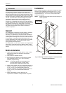
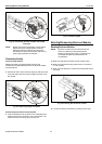
4. Install optional Tamper Switch on cabinet per instructions
in the cabinet installation instructions. Wire Tamper
Switch per job drawings.
5. Mount cabinet door.
CAUTION
Risk of electric equipment damage! Excessive static can
burn out equipment.
► Observe proper anti-static material handling practices
when installing or servicing PC parts and related
components.
► Observe proper equipment and body grounding practices.
► Discharge static electricity from your body before handling
parts.
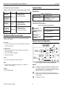
Table 1. Connector terminal specifications
connector terminal pin signal type
input /
output
voltage
type
max.
voltage
max. current
max.
frequency
max. line
impedance
analog input AI input SIGNAL ±12 V ±20 mA 9600 baud 8K ohms
digital input DI input SIGNAL ±10 V ±20 mA -- 15K ohms
analog output AO output
(1
SIGNAL ±10 V ±20 mA 9600 baud 8K ohms
digital output DO output
(2
AC/DC ±24 VAC/DC ±50 mA -- 10K ohms
totalizer output TI input SIGNAL ±12 V ±12 mA 100 Hz
signal ground GND -- -- -- -- -- --
J1 RS-485 (C-BUS)
(3
1 +A input / output SIGNAL ±5 V 1 mA / 180 mA 9600 baud 100 ohms
2 -A input / output SIGNAL ±5 V 1 mA / 180 mA 9600 baud 100 ohms
3S Shield A -- -- -- -- -- --
(1
special application;
(2
regulated;
(3
supervised
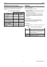
Table 2. Power module models
transformer max. input
model
Vac current draw Hz
(48 VA) controller
VAC output
accessory output convenience outlet
14507287-001 120 0.5 A 60 24 120 Vac, 10A
14507287-002 120 1.7 A 60 24 24 Vac, 100 VA, 24 Vac, 40 VA 120 Vac, 10A
14507287-003 120 1.7 A 60 24 24 Vac, 100 VA, 24 Vdc, 600 mA 120 Vac, 10A
14507287-007 120 120 A 60 24 -- --