


Excel 800 Description of the XCL8010AU Controller Module
11 EN1B-0410GE51 R0908A
4
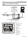
Locate separate from and below all building exhaust
fans and upstream of any prevailing winds.
5
Exhaust to outside of building.
6
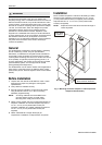
Locate airflow differential switch.
7
Locate UL-listed damper pressure / position indicator
per damper installation instructions.
8
Smoke control must be initiated by a listed fire alarm
control unit or in zone automatic alarm devices and not
devices located outside of the smoke control zone.
Interconnecting wiring must be within 20 ft. (6 meters)
and in conduit.
9
Refer to NFPA 92A.
10
Verify that the AC voltage source connected to the
inside of the main line voltage terminal block is from a
UL-1481 listed uninterruptible power supply. The main
line voltage terminal block maximum current draw is
0.5 A. For 220/240 VAC (60 Hz) applications, verify
that no potential between any conductor and the earth
ground exceeds 150 VAC.
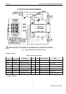
11
All external LONWORKS bus field wiring must be limited
to 4000 ft. (1200 meters) and be terminated to
14506944-001 transient protector (35 V, 290 mA max.)
except C-Bus field wiring communicating at 1 MHZ,
which uses 14502412-014 transient protector (19 V,
500 mA).
12
Panel Bus wiring must be in the same enclosure or
less than 20 ft. to adjacent enclosure. No protection is
required.
Data File Set-Up
Generate the engineering data file for the XL800 Series
Controllers. This data file has a mix of hardware points for the
necessary inputs and outputs to control fans, dampers, and
other equipment. In addition to the inputs and outputs, a
custom control program is written to control the outputs per
the sequence. The XL800 controllers can reset the program
once the data from the operator interface indicates a normal
condition for the dedicated smoke control equipment. Wire
conditions must be programmed to provide annunciation of
trouble conditions.
Also required for a dedicated application for the XL800, is a
weekly time program to test control points, fans, and dampers
by exercising the equipment and verifying feedback
automatically during low building activity periods.
Panel Reset
When in Smoke Control Mode, panel reset is accomplished
by resetting the initiating panel contact circuit or by the
separate initiating/reset switch on the FSCS panel.
CAUTION
Risk of electric equipment damage!
► Failure to use listed/approved replacement parts can
damage product, degrade operation and result in loss of
safety function.
► This product must be installed and operated within its
environmental, mechanical, and electrical specifications as
contained in this document.
► When servicing, use only listed/approved replacement
parts ordered directly from the manufacturer.
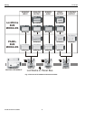
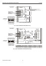
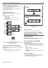
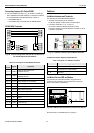
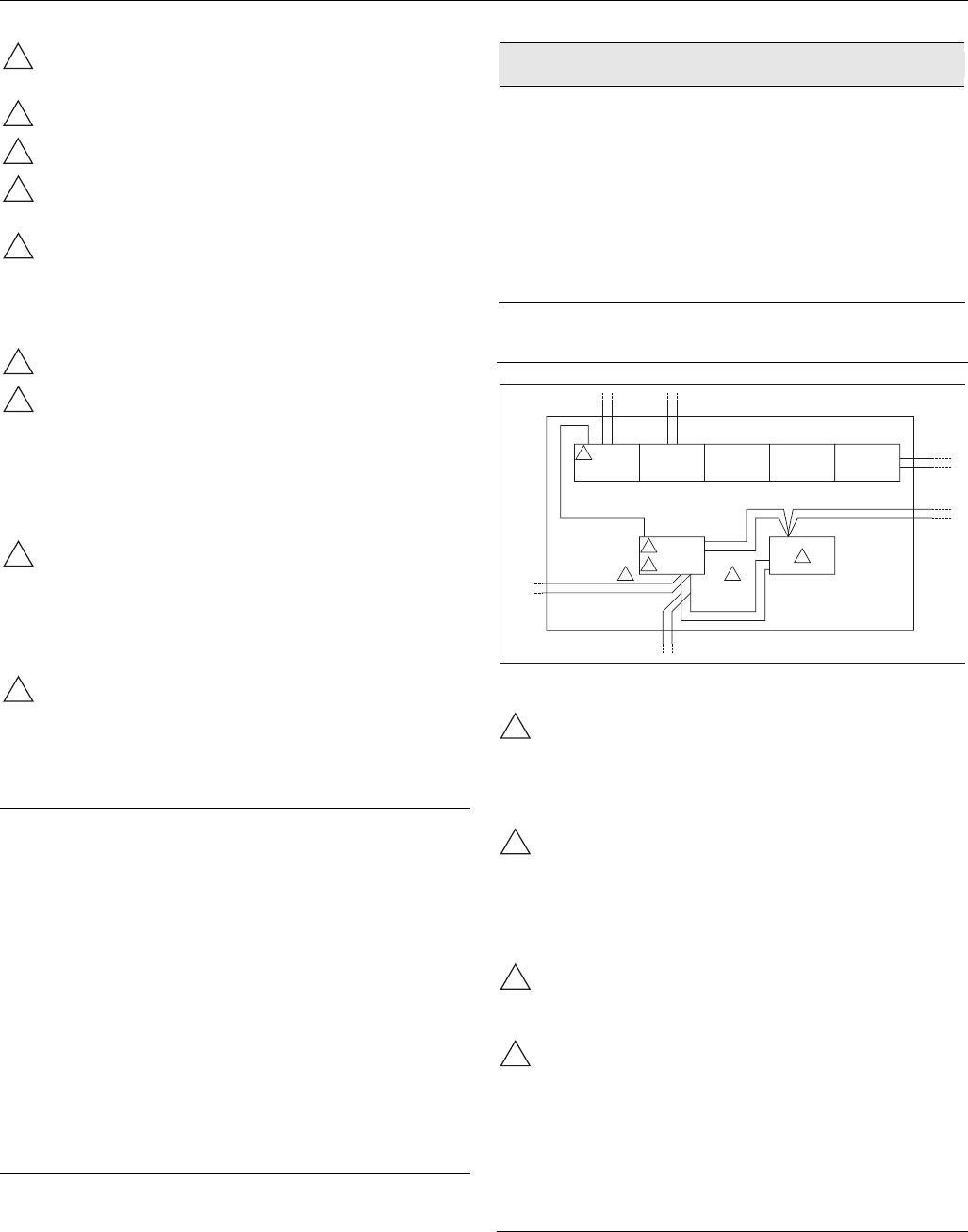
Typical Power Limited Circuit for XL800
ANALOG INPUT
MODULE
CPU
CONTROL
24VAC
ACCESSORY
24VAC
POWER LIMITED
24VAC
ANALOG OUTPUT
MODULE
DIGITAL INPUT
MODULE
DIGITAL OUTPUT
MODULE
2
2
2
3
1 1
POWER
LIMITED
POWER
LIMITED
NON-POWER
LIMITED
NON-POWER
LIMITED
NON-POWER
LIMITED
NON-POWER
LIMITED
Fig. 9. Typical power-limited circuit for XL800
1
14507287-001 through -003 power module accessory
24 VAC output (rated 2A) must be wired in accordance
with NFPA 70, Article 725 when routed within the
cabinet or adjacent cabinets and also for external field
wiring.
2
14507287-001, -002, -003, and -007 control power
module 24 VAC output is inherently power-limited.
Thus, all sourced power from the XL800 controller is
power-limited. All field wiring from these controllers
meet NFPA 70, Article 725 power limited Class II
requirements.
3
If a separate auxiliary power-limited 24 VAC power
source is required, use a control power module
(14507287-001 or -007 control supply).
4
Devices must be installed in areas as shown. All cable
must be routed as shown. All internal power-limited
wiring must be separated by ¼ inch (6 mm) or barrier
from non-power-limited wire. Excess wiring must be
cut, trimmed, and dressed properly to ensure that
proper clearances are maintained.
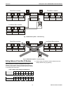
Connecting Single Bus Controller Systems
This section describes how to connect a controller system
which uses Panel Bus I/O modules, only or L
ONWORKS Bus
I/O modules, only.