


Mounting/Dismounting Modules Excel 800
EN1B-0410GE51 R0908A
14
LOCK
4
4
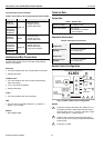
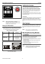
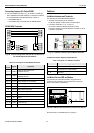
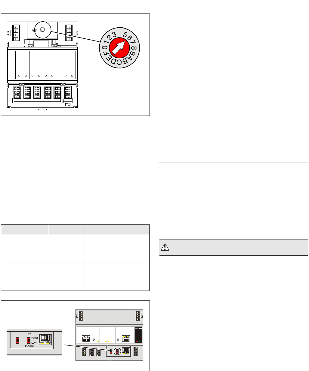
Fig. 14. HEX switch location
NOTE: If the HEX switch setting is changed, the Panel
Bus I/O module will revert to its default
configuration. With L
ONWORKS Bus I/O modules,
the HEX switch is without function.
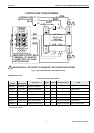
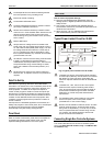
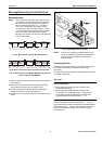
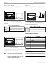
Setting the I/O Bus Switch
► Set the I/O Bus switch S2 of the XCL8010AU Controller
Module depending on the modules connected to terminals
71 ─ 78 and the desired communication as follows:
Table 10. I/O Bus switch settings
communication S2 setting terminals
LONWORKS Bus
only
LON 71 ─ 74 L
ONWORKS Bus
75 ─ 78
LONWORKS Bus
11 ─ 14
LONWORKS Bus
Panel Bus and
L
ONWORKS Bus
Panel 71 ─ 74 Panel Bus
75 ─ 78 Panel Bus
11 ─ 14 L
ONWORKS Bus
Fig. 15. S2 I/O Bus switch
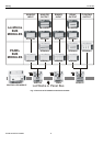
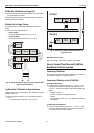
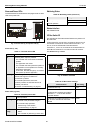
LONWORKS Bus Topologies
The LONWORKS Bus is a 78-kilobit serial link that uses
transformer isolation so that the bus wiring does not have a
polarity. I.e. it is not important which of the two LONWORKS
Bus terminals are connected to each wire of the twisted pair.
The L
ONWORKS Bus does not need to be shielded on the
controller module side.
The LONWORKS Bus can be wired in daisy chain, star, loop or
any combination thereof as long as the maximum wire length
requirements are met.
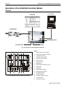
Configuration
The recommended configuration is a daisy chain with two bus
terminations. This layout allows for max. L
ONWORKS Bus
lengths, and its simple structure presents the least number of
possible problems, particularly when adding on to an existing
bus.
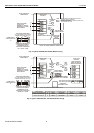
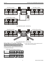
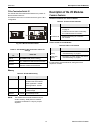
C-Bus Topologies
Via the C-Bus up to 30 C-Bus devices (e.g., controllers, etc.)
can communicate with one another and a PC central. The C-
Bus must be connected via the individual controllers (open
ring).
NOTE: Star connection is not allowed because
uncontrollable line reflections may occur.
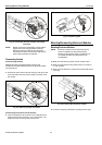
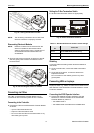
Mounting/Dismounting Modules
WARNING
Risk of electric shock or equipment damage!
► Do not touch any live parts in the cabinet.
► Disconnect the power supply before you start to install the
Excel 800 System.
More than one disconnect switch may be required to de-
energize the system.
► Do not reconnect the power supply until you have
completed the installation.
NOTE: The terminal socket of each I/O module can be
mounted and wired before inserting and locking
the corresponding electronic module.