


Excel 800
3 EN1B-0410GE51 R0908A
WARNING
This equipment generates, uses, and can radiate radio
frequency energy, and if not installed and used in accordance
with the instructions manual, may cause interference to radio
communications. It has been tested and found to comply with
the limits for a Class A computing device pursuant to Subpart
J of Part 15 of FCC Rules, which are designed to provide
reasonable protection against such interference when
operated in a commercial environment. Operation of this
equipment in a residential area is likely to cause interference,
in which case the user, at his own expense, will be required to
take whatever measures may be required to correct the
interference. Any unauthorized modification of this equipment
may result in the revocation of the owner’s authority to
continue its operation.
General
The XL800 Series is designed to provide heating, ventilating
and air-conditioning control. They can operate either
standalone, or networked to Honeywell central workstations
such as EBI. These controllers can also be used for smoke
control system monitoring and control, for monitor and control
of fire (UL864), and general purpose signaling (UL2017). In
UL 2017 applications, the product can be used as a type NM
(Non-Monitored) system. It is also approved for UL916
(Energy Management Equipment.)
The XL800 Series can be used for smoke control applications
when used in conjunction with a UL listed fire alarm control
panel (FACP) and UL listed fire fighters’ smoke control station
(FSCS).
Before Installation
1. Unpack door and remove the XL800 from carton. Check
equipment and report any damage to a Honeywell
representative.
2. Verify cabinet is installed correctly.
3. Securely mount the XL800 to a rigid structural surface
using at least four sets of 1/4 in. (6 mm) mounting
hardware (supplied locally).
NOTE: Anchoring materials must be suitable for the
mounting surface (wood, concrete, steel).
Mounting must comply with all local codes.
4. Obtain correct number and type of sheet metal screws for
subpanel. Installation of a full-size subpanel requires six
no. 10 x ½-inch (13 mm) sheet metal screws (not
supplied). Installation of a smaller subpanel requires four
no. 10 x ½-inch (13 mm) sheet metal screws (not
supplied).
5. Obtain 14505159-001 Tamper Switch per job
requirements. Installation of Tamper Switch is optional.
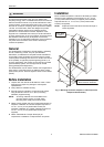
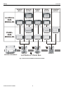
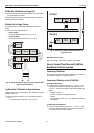
Installation
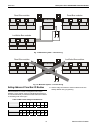
Mount controller subpanel in cabinet so all labeling is visible.
Secure full-size subpanel in place with six no. 10 x ½-inch
(13 mm) sheet metal screws (not supplied). Secure smaller
subpanel with four no. 10 x ½-inch (13 mm) sheet metal
screws (not supplied).
NOTE: Subpanel must mount flat and should not bulge or
recess anywhere.
FULL-SIZE
CABINET
SIX NO. 10 x ½-INCH (13 mm)
SHEET METAL SCREWS
Fig. 1. Mounting controller subpanel in cabinet (full-size
subpanel cabinet shown)