


Excel 800 Description of the I/O Modules
21 EN1B-0410GE51 R0908A
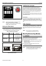
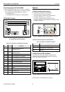
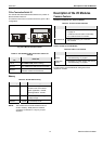
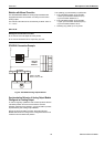
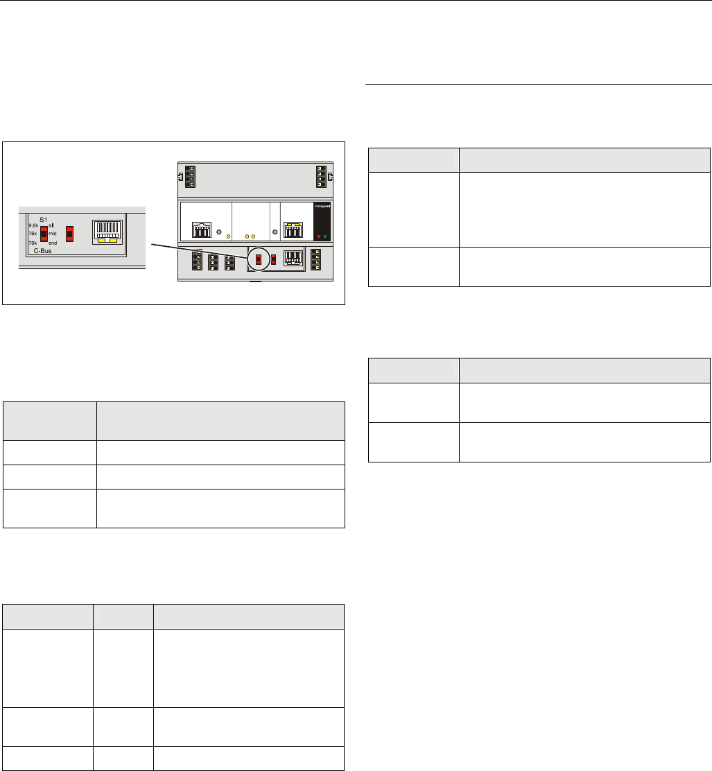
C-Bus Termination Switch S1
The XCL8010AU Controller Module features a 3-position C-
Bus termination switch S1.
This switch must be set in accordance with the given C-Bus
configuration.
Fig. 34. C-Bus termination switch
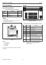
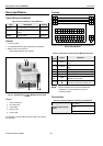
Table 21. XCL8010AU
C-Bus termination switch S1
settings
switch setting
S1
baud rate
9.6k all
Up to 9600 baud (default setting)
76k mid Up to 76800 baud without bus termination
76k end
Up to 76800 baud with bus termination
controller at the end of the C-Bus
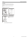
Memory
Table 22. XCL8010AU memory
memory size usage
SRAM 512 KB
For controller application,
modem trend and firmware
RACL application: 128 KB
Total application: 192 KB
Flash 2 MB
Firmware (1 MB) and application
(1 MB) storage
EPROM 128 KB For bootstrap loader
NOTE: The XCL8010AU
Controller Module does not
contain a battery. RAM (data and realtime
clocktime) is buffered for 3 days by a super
capacitor.
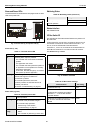
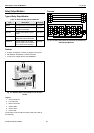
Description of the I/O Modules
Common Features
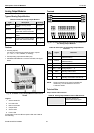
Switches Located on the Terminal Socket
Table 23. Terminal socket switches
feature function
Service button
S1
• LED test, see section "Troubleshooting"
on page 31
• L
ONWORKS service button functionality
for L
ONWORKS Bus I/O modules
Hex switch S2
• Module addressing for Panel Bus
I/O modules
LEDs Located on the I/O Module
Table 24. LEDs on I/O module
feature function
Service LED
(yellow)
• Service information, see section
"Troubleshooting" on page 31
Power LED
(green)
• Information on power supply, see section
"Troubleshooting" on page 31
For the location of these elements, see figures of the
respective modules.