


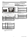

Excel 800 Description of the I/O Modules
29 EN1B-0410GE51 R0908A
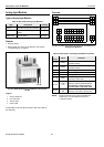
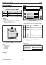
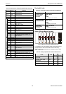
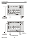
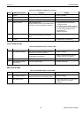
Table 34. Description of Relay Output Module terminals
terminal signal comment
71, 75
COM a
2-wire communication bus
(LON/Panel Bus)
72, 76
COM b
2-wire communication bus
(LON/Panel Bus)
73, 77
24 V~
Power supply
74, 78
24 V~0
Power supply
11
REL1 N.O.
Relay 1 N.O. contact
12
REL1 N.C.
Relay 1 N.C. contact
13
R1 COM
relay 1 common contact
14
R1 COM
For connection of relay 1 common via
cross connector*
21
REL2 N.O.
Relay 2 N.O. contact
22
REL2 N.C.
Relay 2 N.C. contact
23
R2 COM
Relay 2 common contact
24
R2 COM
For connection of relay 2 common via
cross connector*
31
REL3 N.O.
Relay 3 N.O. contact
32
REL3 N.C.
Relay 3 N.C. contact
33
R3 COM
Relay 3 common contact
RELAY BLOCK 1
34
R3 COM
For connection of relay 3 common via
cross connector*
41
REL4 N.O.
Relay 4 N.O. contact
42
REL4 N.C.
Relay 4 N.C. contact
43
R4 COM
Relay 4 common contact
44
R4 COM
For connection of relay 4 common via
cross connector*
51
REL5 N.O.
Relay 5 N.O. contact
52
REL5 N.C.
Relay 5 N.C. contact
53
R5 COM
Relay 5 common contact
54
R5 COM
For connection of relay 5 common via
cross connector*
61
REL6 N.O.
Relay 6 N.O. contact
62
REL6 N.C.
Relay 6 N.C. contact
63
R6 COM
Relay 6 common contact
RELAY BLOCK 2
64
R6 COM
For connection of relay 6 common via
cross connector*
25
Shield connection (functional earth),
internally connected to the DIN rail
* Do not connect by wire!
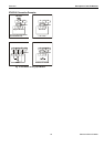
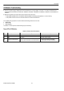
Permissible Loads
Table 35. Permissible loads of Relay Output Modules
max. load
per relay output
module (total)
(common)
24 VAC, 60 Hz
12 A
24 VDC
12 A resistive, 12 A, 0.6 PF
per normally open
contact (common)
24 VAC, 60 Hz
4 A
24 VDC
4 A resistive, 4 A, 0.6 PF
per normally
closed contact
(common)
24 VAC, 2 A, 60 Hz
24 VDC
4 A resistive, 4 A, 0.6 PF
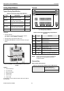
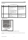
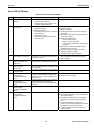
Status LEDs with Manual Overrides
12
3
4
5
6
Honeywell
--1
--0
--AUTO
!
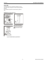
Fig. 46. Manual overrides (toggle switches)
The XFR824AU and XFLR824AU Relay Output Modules are
equipped with six manual overrides: one for each relay
output. These toggle switches can manually be set to either
"auto" or "0" or "1".
Table 36. Relay Output Module status LED behavior
mode LED
N.O.*
(direct)
N.C.*
(reverse)
automatic mode, state
“logical ON”
ON ON OFF
automatic mode, state
“logical OFF”
OFF OFF ON
override mode (setting “0”) flashes OFF ON
override mode (setting “1”) flashes ON OFF
*As configured during engineering.