


Description of the I/O Modules Excel 800
EN1B-0410GE51 R0908A
24
Analog Output Modules
Types of Analog Output Modules
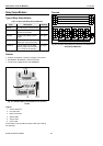
Table 27. Excel 800 Analog Output Modules
type description housing
XF822
Panel Bus Analog Output
Module
light-gray
XFR822
Panel Bus Analog Output
Module with manual overrides
light-gray
XFL822
L
ONWORKS Bus Analog Output
Module
dark-gray
XFLR822
L
ONWORKS Bus Analog Output
Module with manual overrides
dark-gray
XS821-22 terminal socket light-gray
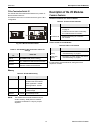
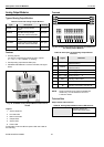
Features
• 8 analog outputs;
can also be configured per output as binary outputs
(0 ─ 10 V, 2 ─ 10 V, ON/OFF, or floating)
• Corresponding output status LEDs (red)
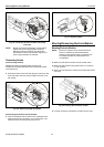
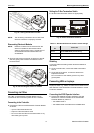
• XFR822AU/XFLR822AU: 8 manual overrides, see figure
below
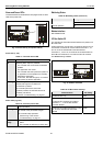
Fig. 38. XF822AU Analog Output Module with terminal
socket
Legend
1 Service button S1
2 Hex switch S2
3 Manual overrides
4 Output LEDs
5 Service LED
6 Power LED
Functionality of service LED and power LED: see Table 42
and following.
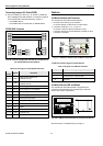
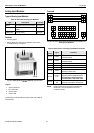
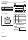
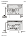
Terminals
Fig. 39. Terminal assignment and internal connections of
the Analog Output Modules
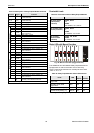
Table 28. Description of the Analog Output Module
terminals
ter-
minal
signal comment
71, 75 COM a
2-wire communication bus
(LON/Panel Bus)
72, 76 COM b
2-wire communication bus
(LON/Panel Bus)
73, 77 24 V~ Power supply
74, 78 24 V~0 Power supply
1 ─ 8 AO1 ─ AO8 Analog outputs 1 ─ 8
9 ─ 18 GND
Ground. All grounds are connected
internally to each other
21, 22 N.C. Do not use!
25, 26
Shield connection (functional earth),
internally connected to the DIN rail
NOTE: Shield connection to be used for shielded I/O
cables only. It is not allowed to connect a
L
ONWORKS shield.
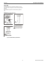
Technical Data
Output status LEDs behavior
Table 29. Analog Output Module status LED behavior
automatic mode brightness follows the
commanded output signal
override mode
flashes