


Description of the I/O Modules Excel 800
EN1B-0410GE51 R0908A
22
Analog Input Modules
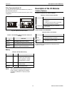
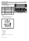
Types of Analog Input Modules
Table 25. Excel 800 Analog Input Modules
type description housing
XF821 Panel Bus Analog Input Module light-gray
XFL821
L
ONWORKS Bus Analog Input
Module
dark-gray
XS821-822 terminal socket light-gray
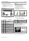
Features
• 8 analog inputs
• Sensor-break and short-circuit detection, see section
"Troubleshooting" on page 31.
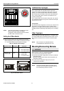
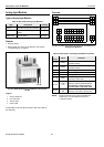
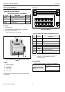
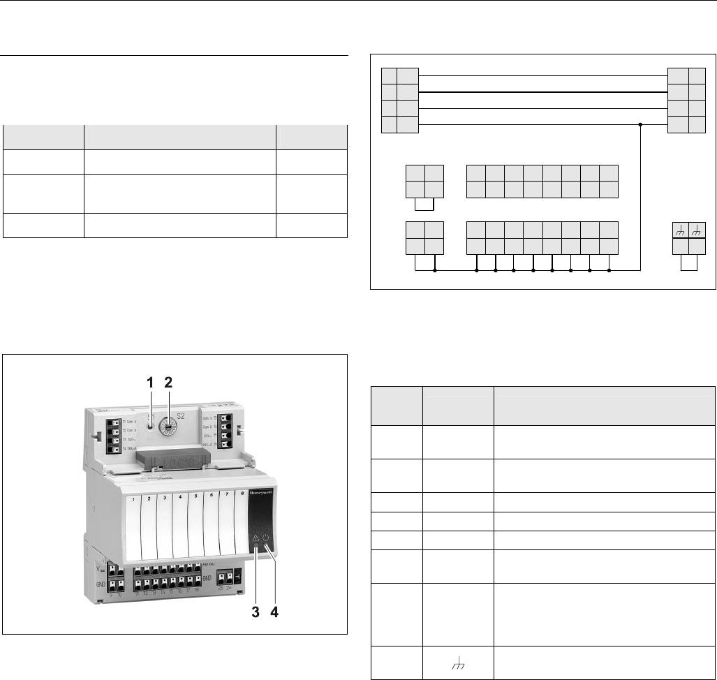
Fig. 35. XF821AU Analog Input Module with terminal
socket
Legend
1 Service button S1
2 Hex switch S2
3 Service LED
4 Power LED
Functionality of service LED and power LED: see Table 42
and following.
Terminals
25 26
74
78
73 77
72 76
71
75
24
V~
24
V~
24
V~0
24
V~0
COM
B
COM
B
COM
A
COM
A
AI8
8
AI7
7
AI6
6
AI5
5
AI4
4
AI3
3
AI2
2
AI1
1
18171615141312
GND
11
GNDGNDGNDGNDGNDGNDGND
22
V
21
10
GND
9
GND
AUX
V
AUX
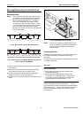
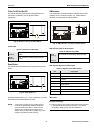
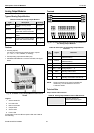
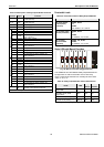
Fig. 36. Terminal assignment and internal connections of
Analog Input Modules
Table 26. Description of Analog Input Module terminals
ter-
minal
signal comment
71, 75 COM a
2-wire communication bus
(LON/Panel Bus)
72, 76 COM b
2-wire communication bus
(LON/Panel Bus)
73, 77 24 V~ Power supply
74, 78 24 V~0 Power supply
1 ─ 8 AI1 ─ AI8 Analog inputs 1 ─ 8
9 ─ 18 GND
Ground. All grounds are connected
internally to each other
21, 22
10 VDC /
5 mA
Auxiliary voltage signal (used e.g. for
supplying setpoint potentiometers).
Connections to these terminals
must be made in the same room.
25, 26
Shield connection (functional earth),
internally connected to the DIN rail
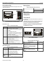
NOTE: Shield connection to be used for shielded I/O
cables only. It is not allowed to connect a
L
ONWORKS shield.