


Excel 800 Mounting/Dismounting Modules
19 EN1B-0410GE51 R0908A
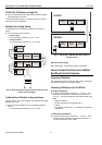
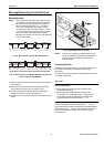
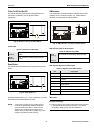
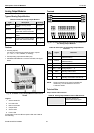
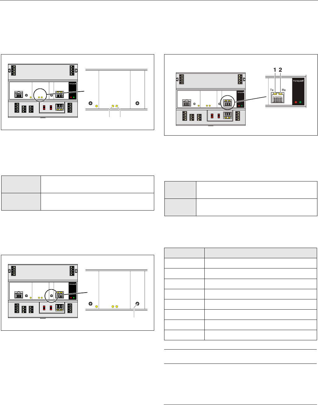
C-Bus Tx LED and Rx LED
The XCL8010AU Controller Module is equipped with a Tx
LED (status: yellow/OFF) and an Rx LED (status:
yellow/OFF).
1
C-Bus
2
Fig. 29. C-Bus Tx LED (1) and Rx LED (2)
C-Bus LEDs
Table 14. Controller C-Bus LEDs
Tx (1)
flickering
The controller is sending data onto the
C-Bus
Rx (2)
flickering
The controller is receiving data from the
C-Bus
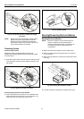
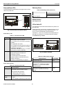
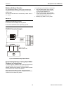
Reset Button
The XCL8010AU Controller Module is equipped with a reset
button.
1
RESET
Fig. 30. Reset button (1)
Pushing the reset button (1), e.g. using a paperclip, will cause
the XCL8010AU
Controller Module to reset.
NOTE: In the event of a reset, all non-volatile memory
contents are permanently deleted, though the
clock will not be set to zero. In order to avoid
problems, we therefore recommend that you
always save your application changes (e.g., time
program changes) to FLASH memory.
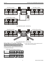
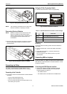
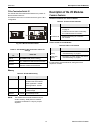
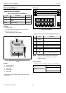
HMI Interface
The XCL8010AU Controller Module is equipped with an HMI
Interface for the connection of HMIs, e.g., XI582 Operator
Interface or a laptop (with XL-Online/CARE).
Fig. 31. HMI interface, Tx LED (1) and Rx LED (2)
HMI interface LEDs on RJ45 socket
Table 15. HMI interface LEDs
Tx (1)
flickering
The controller is transmitting data to the HMI
Rx (2)
flickering
The controller is receiving data from the HMI
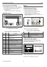
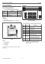
HMI interface Signals on RJ45 socket
Table 16. Signals of the HMI interface
pin signal type
1 -
2 Receive
3 Transmit
4 -
5 Signal ground
6 -
7 5 V
8 -
NOTICE
Equipment damage!
► If earth grounding is required, make sure that only terminal
2 is connected to earth ground. Terminal 1 must not be
connected to earth ground. See also Appendix 1.