


Mounting/Dismounting Modules Excel 800
EN1B-0410GE51 R0908A
20
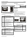
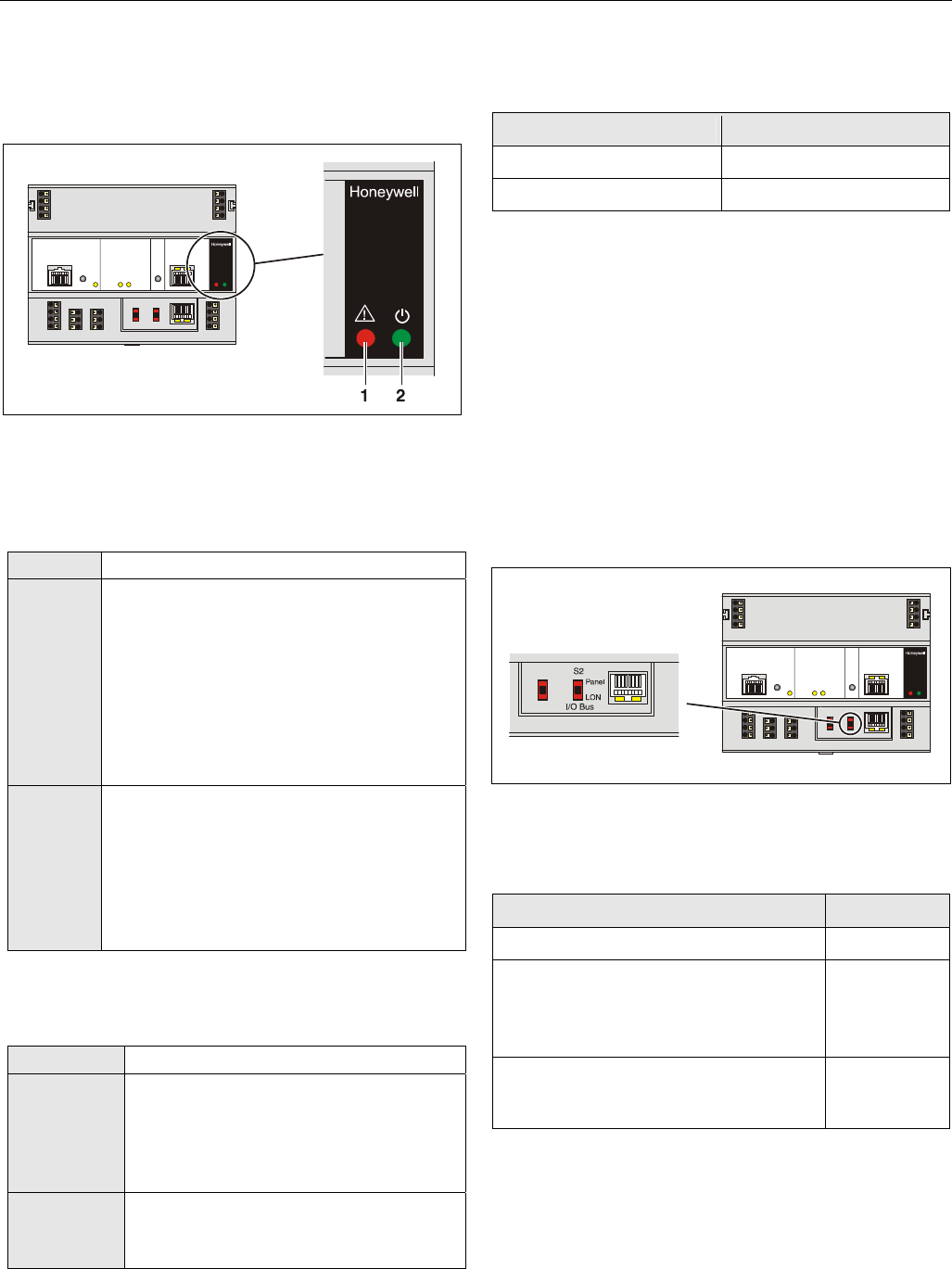
Alarm and Power LEDs
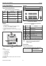
The XCL8010AU Controller Module is equipped with an alarm
LED and a power LED.
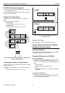
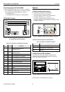
Fig. 32. Alarm LED (1) and power LED (2)
Alarm LED (1, red)
Table 17. Controller alarm LED
Off
Normal operation
On
Watchdog alarm output is powered
• The controller has encountered a hardware
problem
• The application has a fault
• The controller has been powered up without
an application or the operator has manually
stopped the application.
In this case, the LED will light up 13 minutes
after power-up without application
Flashing The watchdog alarm output has not yet been
powered, although the controller has
encountered a problem.
The controller performs a warm start.
If problem persists, the LED will become lit
constantly, see above.
See section "Troubleshooting" on page 31.
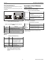
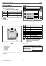
Power LED (2, green)
Table 18. Controller power LED
On
Normal operation
Flashing One or more of the internal voltage supplies
are outside of the permissible ranges.
The controller stops operation.
► Check wiring or see section
"Troubleshooting" on page 31.
Goes out
briefly
• The operator has activated the reset
button
• The controller is performing a warm start
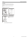
Watchdog Status
Table 19. Watchdog status (terminal 4)
status signal on terminal 4
Failure (= alarm) 24 V
Normal operation 0 V
Modem Interface
NO CONNECTION.
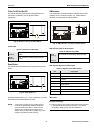
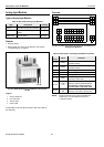
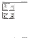
I/O Bus Switch S2
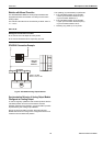
The XCL8010AU Controller Module features a 2-position I/O
Bus switch S2.
I/O Bus switch S2 must be set in accordance with the kind of
I/O modules connected to communication terminals 71, 72
and 75, 76 of the XCL8010AU Controller Module.
Terminals 71, 72 and 75, 76 must be all connected either to
Panel Bus I/O modules or to L
ONWORKS Bus I/O modules.
The default setting is Panel.
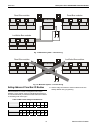
Fig. 33. I/O Bus switch S2
Table 20. I/O Bus switch settings
communication S2 setting
LONWORKS Bus only LON
Panel Bus and LONWORKS Bus
L
ONWORKS BUS modules connected to
terminals 11 ─ 14 of the XCL8010AU
Controller Module
Panel
Panel Bus connected to terminals 71, 72 or
75, 76 of the XCL8010AU Controller
Module
Panel