


Heatilator • RAVE4013I-C • 2293-900 Rev. C • 8/1258
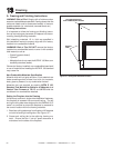
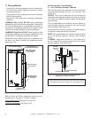
Figure 14.2 Air Shutter
F. Install the Mesh
The mesh front is included with the Deco and Illusion
fronts.
1. Remove fi xed glass assembly as instructed.
2. Place glass assembly into mesh screen such that the
four mesh clips attached to the mesh assembly snap
into the four corresponding slots on the fi xed glass as-
sembly.
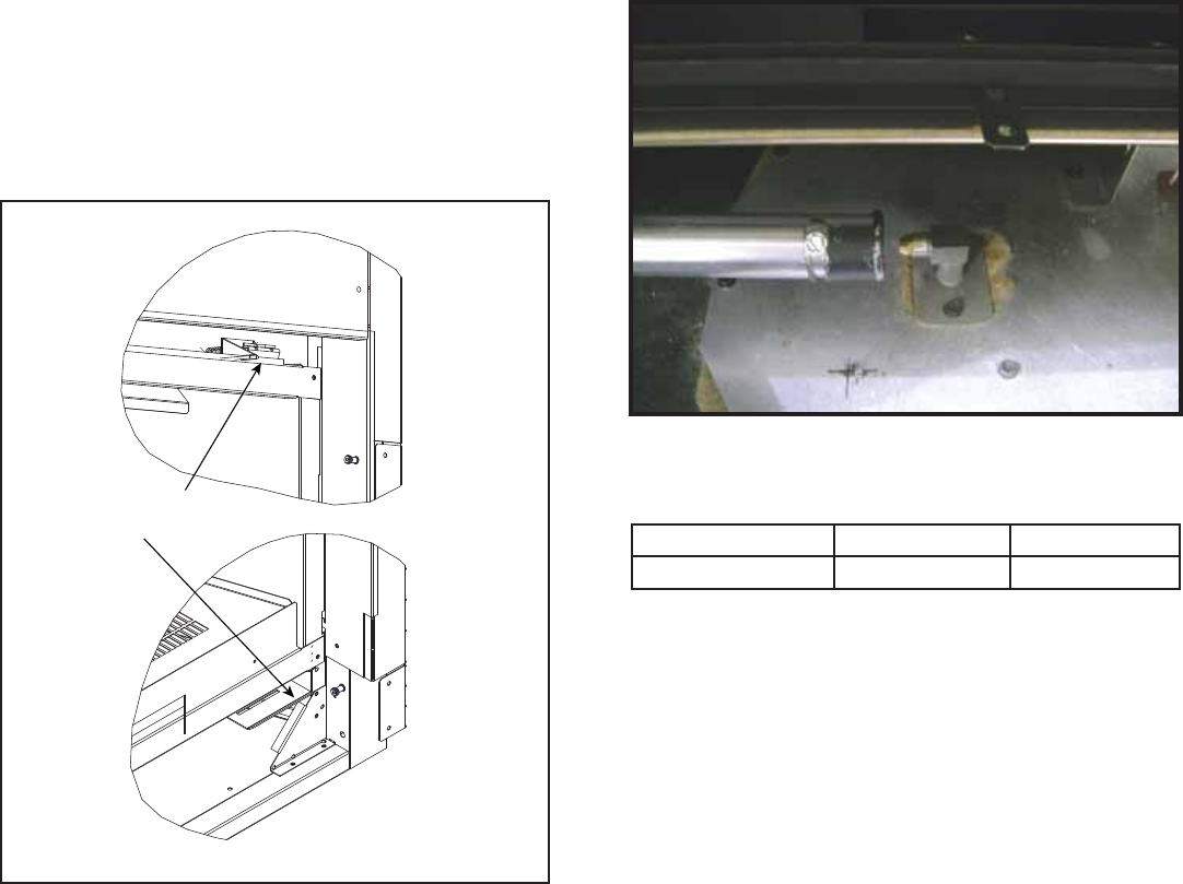
G. Air Shutter Setting
Air shutter settings may be adjusted by a qualifi ed install-
er at the time of installation. The air shutter is set at the
factory for minimum vertical vent run. Adjust air shutter for
longer vertical runs. See Figure 14.2.
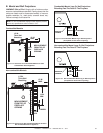
• Loosen the 1/4 in. screw.
• Twist shutter to adjust.
• Shutter may be opened for longer horizontal vent runs.
• Do not close the air shutter more than the settings
specifi ed below.
• Tighten the screw.
NOTICE: If the fl ames appear to be orange, open the air
shutter to prevent residue buildup on the glass.
Air Shutter Settings
NG LP
RAVE4013I-C 3/16 in. 9/16 in.
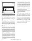
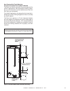
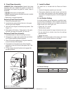
Figure 14.1 Fixed Glass Assembly
E. Fixed Glass Assembly
WARNING! Risk of Asphyxiation! Handle fi xed glass
assembly with care. Inspect the gasket to ensure it is
undamaged and inspect the glass for cracks, chips or
scratches.
• DO NOT strike, slam or scratch glass.
• DO NOT operate fi replace with glass removed, cracked,
broken or scratched.
• Replace as a complete assembly.
Removing Fixed Glass Assembly
1. Remove the decorative front.
2. Locate the two spring latches that are on the upper
left and right of the fi replace.
3. Use both index fi ngers to release spring latches. See
Figure 14.1.
4. Allow glass to tilt forward. Grasp glass on the upper
right and left sides and lift glass “up” and “out.”
Replacing Fixed Glass Assembly
1. Locate glide tabs on lower left and right corners.
2. Grasp glass on upper right and left sides and tilt bot-
tom of glass assembly toward fi replace.
3. Allow of the bottom gasketing of the glass assembly
to touch the face of the fi replace.
4. Put pressure on the glass as you allow the glass
assembly to drop into the two lower glass clips. See
Figure 14.1.
5. Tilt top of glass towards fi replace and engage both
top spring latches
LOWER GLASS CLIP
UPPER SPRING LATCH