


17Heatilator • RAVE4013I-C • 2293-900 Rev. C • 8/12
5
5
Framing and Clearances
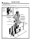
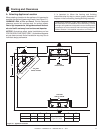
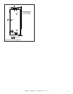
A. Selecting Appliance Location
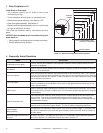
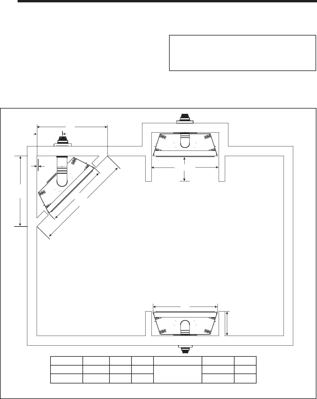
When selecting a location for the appliance it is important to
consider the required clearances to walls (see Figure 5.1).
WARNING! Risk of Fire or Burns! Provide adequate
clearance around air openings and for service access.
Due to high temperatures, the appliance should be locat-
ed out of traffi c and away from furniture and draperies.
NOTICE: Illustrations refl ect typical installations and are
FOR DESIGN PURPOSES ONLY. Illustrations/diagrams
are not drawn to scale. Actual installation may vary due to
individual design preference.
1 IN.
A
E
A
B
C
TOP VENT
ONE 90
0
ELBOW
ALCOVE
INSTALLATION
D*
TOP VENT
ONE 90° ELBOW
B
F
Figure 5.1 Appliance Locations
ABC D E F
Inches 53-1/32 48 75
See Section D.
Figure 5.5 & 5.6
19-9/32 17-3/4
Millimeters 1347 1218 1905 490 451
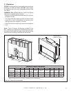
Unlike many traditional, single sided Heatilator fi replaces,
the RAVE4013I-C is recessed into surround framing. The left
and right nailing tabs were designed to ensure the fi replace is
recessed to the correct location within the framing materials.
Refer to Section 13 for detailed instructions on fi nishing.
It is important to follow the framing and fi nishing
instructions step by step to ensure proper placement of
fi replace in the surrounding framing/fi nishing materials.