


Heatilator • RAVE4013I-C • 2293-900 Rev. C • 8/1246
A. Fuel Conversion
• Make sure the appliance is compatible with available gas
types.
• Conversions must be made by a qualified service
technician using Hearth & Home Technologies specifi ed
and approved parts.
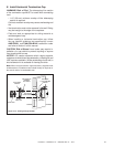
B. Gas Pressure
• Optimum appliance performance requires proper input
pressures.
• Gas line sizing requirements will be determined in ANSI
Z223.1 National Fuel Gas Code in the USA and CAN/
CGA B149 in Canada.
• Pressure requirements are:
WARNING! Risk of Fire or Explosion! High pressure
will damage valve. Low pressure may cause explosion.
• Verify inlet pressures. Verify minimum pressures when
other household gas appliances are operating.
• Install regulator upstream of valve if line pressure is
greater than 1/2 psig.
11
11
Gas Information
Gas Pressure Natural Gas Propane
Minimum inlet pressure 5.0 in. w.c. 11.0 in. w.c.
Maximum inlet pressure 10.0 in. w.c. 13.0 in. w.c.
Manifold pressure 3.5 in. w.c. 10.0 in. w.c.
Fire Risk.
Explosion Hazard.
High pressure will damage valve.
• Disconnect gas supply piping BEFORE
pressure testing gas line at test pressures
above 1/2 psig.
• Close the manual shutoff valve BEFORE
pressure testing gas line at test pressures
equal to or less than 1/2 psig.
WARNING
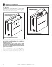
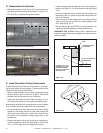
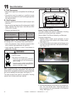
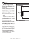
Note: This appliance does include a manual gas shutoff valve
that is located in the valve compartment. This manual gas
shutoff valve is accessible for service by removing the base
pan, burner assembly and valve plate. See Figure 11.1.
The lower access cover panel is removable if fi nishing
material has not been previously installed.
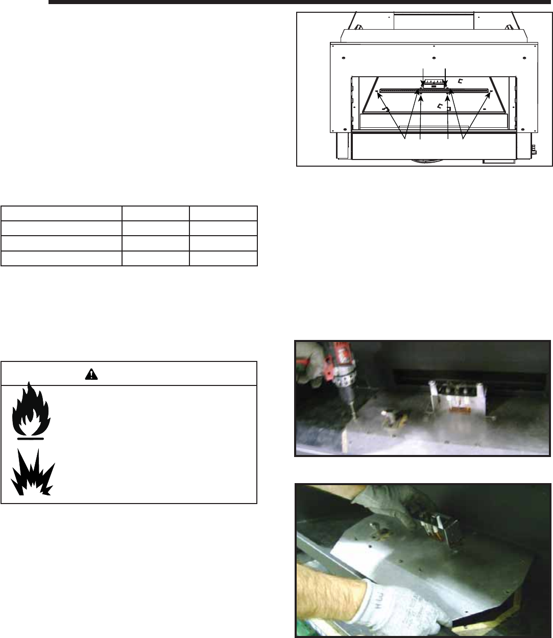
Figure 11.1 Cover Tray Removal
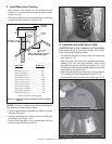
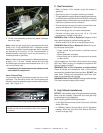
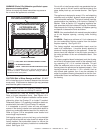
Figure 11.2. Remove Valve Plate Screws
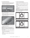
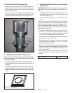
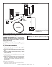
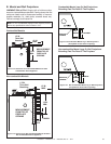
3. Set the valve bracket on the front lip of the fi rebox bot-
tom. Turn “off” the ball valve. Disconnect gas valve
from the gas fl ex ball valve assembly at the pressure
fi tting. See Figure 11.4.
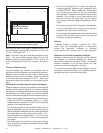
Figure 11.3. Remove Valve Plate
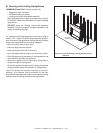
Access Through the Valve Assembly
The lower access cover panel is removable if fi nishing
material has not been previously installed.
Remove Media Tray, Burner Assembly, and Base pan.
To access components:
1. Remove eleven screws around perimeter of valve
plate that secure valve plate to the fi rebox bottom.
See Figure 11.2.
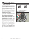
2. Lift the valve plate from the back so that the gas valve
can clear the valve plate hole in the bottom the fi rebox.
See Figure 11.3.
MEDIA TRAY/BASE PAN
ASSEMBLY SCREWS
PILOT BRACKET SCREWS