


49Heatilator • RAVE4013I-C • 2293-900 Rev. C • 8/12
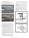
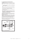
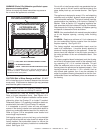
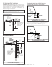
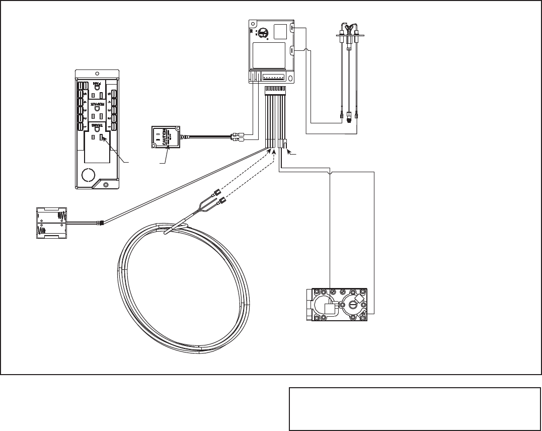
Figure 12.2 IntelliFire Pilot Ignition (IPI) Wiring Diagram with Wall Switch or Thermostat
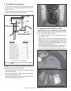
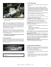
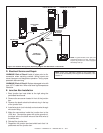
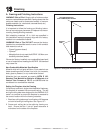
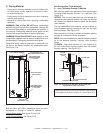
E. Junction Box Installation
1. Bend junction box heat shield to the right along the
perforated hand bends.
2. Remove the one screw located in front of the junction
box.
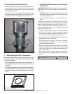
3. Remove the plastic electrical knockout slug in the top
of the junction box.
4. Install wire strain (not included) and route wire through
wire strain fi tting.
5. Make the connections inside the junction box to the
120V wire. Connect the green wire to the ground nut,
the black wire to the black wire and the white wire to
the white wire.
6. Reinstall the junction box.
7. Reposition the junction box heat shield such that it is
positioned over the junction box.
TRANSFORMER
3 VAC
PLUG IN
BLACK
RED
BATTERY PACK
THERMOSTAT
WIRE ASSEMBLY
WIRES
(TO BROWN)
ORANGE
GREEN
VALVE
WHITE
ORANGE
IGNITION MODULE 3 VAC INTERMITTENT PILOT IGNITOR
HOT
NEUTRAL
I
S
GROUND TO
FIREPLACE
CHASSIS
NOTE: 1. Ignition module, valve, pilot, and
wall switch operate on 3 volts. 120 VAC is
required at junction box unless equipped
with battery back-up.
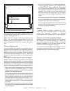
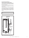
D. Electrical Service and Repair
WARNING! Risk of Shock! Label all wires prior to dis-
connection when servicing controls. Wiring errors can
cause improper and dangerous operation. Verify proper
operation after servicing.
WARNING! Risk of Shock! Replace damaged wire with
type 105° C rated wire. Wire must have high temperature
insulation.
Note: There is an alternative access to the junction box.
This can be accessed by removing the valve assembly. See
Section 11.