


19
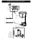
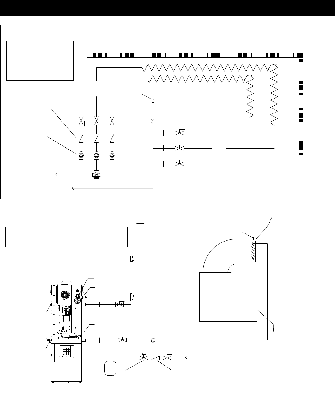
AIR VENT (TYPICALLY
INSTALLED IN THE HIGHEST
ACCESSABLE LOCATION IN
THE PIPING)
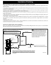
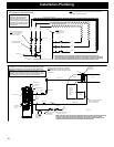
(LOW TEMPERATURE) RADIANT FLOOR HEAT
(LOW TEMPERATURE) RADIANT FLOOR HEAT
FROM BOILER
SYSTEM SUPPLY 3/4"
SYSTEM RETURN 3/4"
HOT
THERMOSTATIC
MIXING VALVE
TO BOILER
COLD
MIX
UNION
SHUT-OFF VALVE
NOTE: IF CIRCULATOR DOES NOT HAVE
CHECK VALVE THEN A FLOW CONTOL
VALVE WILL ALSO BE NEEDED AND
INSTALLED IN THIS LOCATION
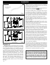
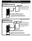
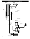
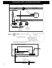
EXAMPLE OF A COMBINATION HIGH/LOW MULTI-ZONE HEATING SYSTEM
WITH INDIVIDUAL ZONE CIRCULATORS
CIRCULATORS WITH INTEGRAL
CHECK VALVE (SEE NOTE)
SHUT-OFF VALVE
(HIGH TEMPERATURE) BASEBOARD HEAT
ZONE 1
ZONE 2
ZONE 3
AIR VENT
ZONE 1
NOTE: ALWAYS REFER TO THE INDIVIDUAL COMPONENTS RECOMMENDED
INSTALLATION INSTRUCTIONS FOR THE PROPER MOUNTING POSITION AND
LOCATION WITHIN THE PIPING SYSTEM.
ZONE 2
ZONE 3
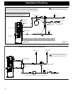
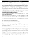
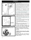
NOTICE: When installing with the
Atmospheric Conversion, all of the
pressurized system components
shown are not necessary. Air vents or
bleeders should be removed from the
plumbing system to prevent air from
entering the lines. Control dipswitch
#6 must be “ON”.
NOTE: Cold return water temperature (Sustained temperatures below 140 degrees
Fahrenheit) will lead to condensation or moisture in the firebox. This moisture can lead to
creosote formation. To help minimize moisture and creosote, it is strongly recommended
that some method of temperature balance is incorporated into the return system.
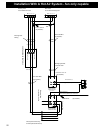
EXISTING
GAS / OIL
FURNACE
OR
ELECTRIC
HEAT
PUMP
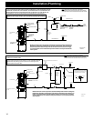
NOTE: NEVER INSTALL HOT WATER
COIL ON THE RETURN SIDE
OF THE HEATING SYSTEM
* ITEMS SUPPLIED
PRESSURE REDUCING VALVE
(PRV) OR COMBINATION
PRV AND RELIEF VALVE
* BOILER DRAIN,
3/4" NPT MALE X
3/4" HOSE
* 3/4" NPT MALE PLUG
PIPE TO
WITHIN 6" OF
THE FLOOR
OR A FLOOR
DRAIN
UNION
COLD
WATER
SUPPLY 1/2"
SHUT-OFF VALVE
CHECK VALVE (OR BACKFLOW
PREVENTER IF REQUIRED)
SHUT-OFF VALVE
CIRCULATOR
RETURN
AIR FLOW
SYSTEM RETURN 3/4"
HOT WATER
HEATING COIL
TO BE SIZED
BY INSTALLER
EXAMPLE OF A TYPICAL FORCED HOT AIR HEATING SYSTEM
WITH THE BOILER DIRECT TO AN IN DUCT HOT WATER COIL
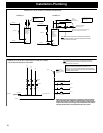
NOTE: ALWAYS REFER TO THE INDIVIDUAL COMPONENTS
RECOMMENDED INSTALLATION INSTRUCTIONS FOR THE
PROPER MOUNTING POSITION AND LOCATION WITHIN THE
PIPING SYSTEM.
* AUTOMATIC AIR VENT
* PRESSURE RELIEF VALVE
* TEMP/PRESSURE
GAUGE
SYSTEM SUPPLY 3/4"
AIR VENT
AIR FLOW
AIR FLOW
UNION
SHUT-OFF
VALVE
EXPANSION TANK
(DIAPHRAGM TYPE)
FLOW CHECK
PURGE & BALANCE
VALVE
(SIZED FOR TOTAL
SYSTEM VOLUME)
NOTICE: When installing with the Atmospheric Conversion, all of the
pressurized system components shown are not necessary. Air vents
or bleeders should be removed from the plumbing system to prevent
air from entering the lines. Control dipswitch #6 must be “ON”.
NOTE: Cold return water temperature (Sustained temperatures below 140 degrees Fahrenheit)
will lead to condensation or moisture in the firebox. This moisture can lead to creosote
formation. To help minimize moisture and creosote, it is strongly recommended that some
method of temperature balance is incorporated into the return system.