


Heat & Glo • ST-36TR-IPI, PIER-36TR-IPI • 2176-900 Rev. F • 8/11 59
Note: All
measurements
in inches.
MEASUREMENTS FROM
TOP EDGE OF THE OPENING
5
10
11
12
2-1/2
13
14
15
16
17
18
19
32
TO CEILING
9
10
11
12
8
7
6
5
4
3
25
18
Note: All
measurements
in inches.
MEASUREMENTS FROM
TOP EDGE OF THE OPENING
5
10
11
12
1
13
14
15
16
17
18
19
32
TO CEILING
9
10
11
12
8
7
6
5
4
3
25
18
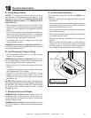
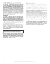
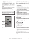
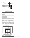
B. Mantel and Wall Projections
WARNING! Risk of Fire! Comply with all minimum clear-
ances as specifi ed. Framing closer than the minimums list-
ed must be constructed entirely of noncombustible materi-
als (i.e., steel studs, concrete board, etc.) Failure to comply
could cause fi re.
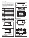
Figure 13.12 Minimum Vertical and Maximum Horizontal
Dimensions of Combustibles
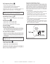
Figure 13.13 Minimum Vertical and Maximum Horizontal
Dimensions of Combustibles
MEASUREMENTS FROM
TOP EDGE OF THE OPENING
10
11
12
18
9
8
7
6
1
2
3
4
5
6
12
32
MAX.
MIN.
TO CEILING
MEASUREMENTS FROM
TOP EDGE OF THE OPENING
4
32
8
9
10
12
7
6
6
7
8
9
10
12
MAX.
MIN.
TO CEILING
Note: All
measurements
in inches.
Note: All
measurements
in inches.
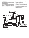
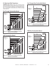
Figure 13.14 Minimum Vertical and Maximum Horizontal
Dimensions of Non-Combustibles
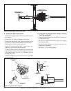
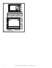
Figure 13.15 Minimum Vertical and Maximum Horizontal
Dimensions of Non-Combustibles
See-Through Combustible Mantel
PIER Combustible Mantel
PIER Non-Combustible Mantel
See-Through Non-Combustible Mantel