


Heat & Glo • ST-36TR-IPI, PIER-36TR-IPI • 2176-900 Rev. F • 8/11 31
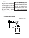
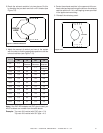
Figure 7.10
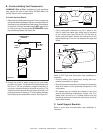
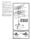
4. Center the exhaust restrictor in the open end of the ex-
haust outlet and secure through the slots on the exhaust
restrictor with the 2-1/4 in. self tapping screws provided
in the appliance manual bag.
5. Reinstall the refractory panel.
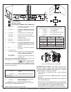
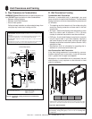
3. Match the amount of vertical you have in the system
with the chart to fi nd the appropriate position to set the
exhaust restrictor (see Figure 7.10).
1 2 3 4 5
SETTINGS
1 2 3 4 5
Vertical
TOP VENT REAR VENT
NG LP NG LP
4 ft. 1-1
No
Restrictor
No
Restrictor
No
Restrictor
8 ft. 2-2 1-2 1-1
No
Restrictor
15 ft. 3-3 3-2 2-2 1-2
20 ft. 3-4 3-3 3-3 2-3
25 ft. 3-4 3-3 3-3 2-3
30 ft. 4-4 3-4 3-4 3-3
35 ft. 4-4 3-4 3-4 3-3
40 ft. 5-4 4-4 4-4 3-4
45 ft. 5-4 4-4 4-4 3-4
50 ft. 5-5 5-4 5-4 4-4
55 ft. 5-5 5-4 5-4 4-4
Note: If the DVP-2SL adapter and SLP pipe is used, you
MUST subtract one number from the table above.
Example: Top vent 40 ft vertical with DVP pipe = 5-4
Top vent 40 ft vertical with SLP pipe = 4-3
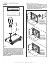
Figure 7.9 Exhaust Restrictor
2. Break the exhaust restrictor into two pieces. Do this
by bending the part back and forth until it breaks (see
Figure 7.9).
BREAK
HERE