


Heat & Glo • ST-36TR-IPI, PIER-36TR-IPI • 2176-900 Rev. F • 8/11 55
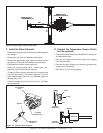
I. Setting Flame Height/Manifold Pressure
(To be done by a qualifi ed service technician.) Upon initial
power-up of this device, valve pressure must be set for
fl ame adjustment.
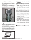
• Loosen output pressure tap on valve and connect with
pressure manometer.
• Press fl ame button once (see Figure 12.4); fi replace will
light with fl ames on high.
• Turn solenoid clockwise to increase pressure,
counterclockwise to decrease pressure until manifold
pressure on high is 3.5 in. water column for natural gas
(NG), 10.0 in. water column for propane (LP).
• Once pressure is achieved spin jam nut on solenoid step
tight against regulator face to prevent rotation. Do not
overtighten.
• Press fl ame button twice to turn fi replace off.
• Remove manometer tube and tighten or close pressure
tap. Use a commercially available, non-corrosive leak
check solution to carefully check the pressure tap for
leaks. Be sure to rinse off all leak check solution following
testing.
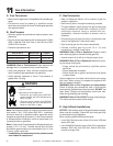
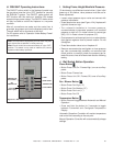
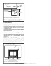
Figure 12.4 Wall Switch
J. Wall Switch Button Operation
Flame Button
• Button Press: Unit On / Flames High, turns on auxiliary
power
• Button Press: Flames Low
• Button Press: Unit Off / Flames Off, turns off auxiliary
power
Fan / Blower Button
• Button Press: Fan High (“3”)
• Button Press: Fan Medium (“2”)
• Button Press: Fan Low (“1”)
• Button Press: Fan Off
Temperature Button
• Button Press will toggle between Automatic and Manual
Operation.
• Press and Hold the button for 3 seconds to toggle
between Fahrenheit and Centigrade Temperature
Display.
Automatic Operation: Controller will monitor temperature
and control unit according to the set point.
Manual Operation: Controller will not automatically change
settings.
Note: The temperature displayed by the wall switch may take
up to 30 minutes to stabilize on initial power-up.
Note: Check control box and assure switch is in the “OFF”
position. This switch is only used on Intellifi re (IPI) control
systems under battery operation.
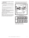
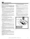
H. WSK-MLT Operating Instructions
The ON/OFF rocker switch in the fi replace (located near
the gas valve) must be in the “OFF” position for use with
the WSK-MLT system. The ON/OFF rocker switch will
NOT function with this device on Intellifi re (IPI) models
except during a power outage. The ON/OFF rocker switch
will only be used to control the fi replace in a no-power
condition.
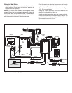
After all connections are made and the control box is
grounded, plug power cord into the fi replace junction box.
The wall switch will be functional at this time.
For IPI system, refer to “Operation Under Battery Power”
for instructions.
FLAME
FAN/BLOWER
TEMPERATURE
COLD CLIMATE
TEMPERATURE
ADJUSTMENT
SET
TEMPERATURE
AUXILIARY
(Ember Lights)