


Heat & Glo • ST-36TR-IPI, PIER-36TR-IPI • 2176-900 Rev. F • 8/11 51
A. Wiring Requirements
NOTICE: This appliance must be electrically wired
and grounded in accordance with local codes or, in the
absence of local codes, with National Electric Code
ANSI/NFPA 70-latest edition or the Canadian Electric
Code CSA C22.1.
• Wire the appliance junction box to 110-120 VAC. This is
required for use of optional accessories (standing pilot
ignition) or proper operation of the appliance (IntelliFire
ignition).
• A 110-120 VAC circuit for this product must be protected with
ground-fault circuit-interrupter protection, in compliance
with the applicable electrical codes, when it is installed in
locations such as in bathrooms or near sinks.
• Low voltage and 110 VAC voltage cannot be shared
within the same wall box.
WARNING! Risk of Shock or Explosion! DO NOT wire
110V to the valve or to the appliance wall switch. Incorrect
wiring will damage controls.
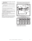
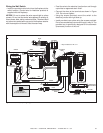
B. IntelliFire Ignition System Wiring
• Wire the appliance junction box to 110 VAC for proper
operation of the appliance.
WARNING! Risk of Shock or Explosion! DO NOT wire
IPI controlled appliance junction box to a switched circuit.
Incorrect wiring will override IPI safety lockout.
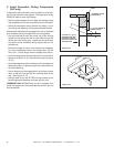
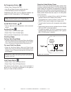
• Refer to Figure 12.2, IntelliFire Pilot Ignition (IPI) Wiring
Diagram.
• This appliance is equipped with an IntelliFire control valve
which operates on a 3 volt system.
• Plug the 110 VAC plug from the WSK-MLT into the
appliance junction box to supply power to the unit OR
install two D cell batteries (not included) into the battery
pack before use.
NOTICE: Batteries should not be placed in the battery pack
while using the transformer. Remove batteries before using
the WSK-MLT, and unplug the WSK-MLT before installing
the batteries. Battery polarity must be correct or module
damage will occur.
C. Electrical Service and Repair
WARNING! Risk of Shock! Label all wires prior to dis-
connection when servicing controls. Wiring errors can
cause improper and dangerous operation. Verify proper
operation after servicing.
WARNING! Risk of Shock! Replace damaged wire with
type 105° C rated wire. Wire must have high temperature
insulation.
12
12
Electrical Information
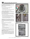
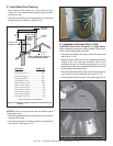
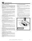
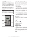
ROMEX CONNECTORS
Figure 12.1 Junction Box Detail
NOTICE: DO NOT wire
110 VAC to wall switch.
D. Junction Box Installation
The junction box must be wired from the INSIDE of the
appliance:
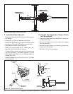
• Determine which side of the appliance the junction box
is located on.
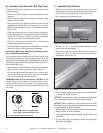
• Pull the electrical wires from outside the appliance through
the knockout making sure to use a Romex connector to
fasten the electrical wires to the unit.
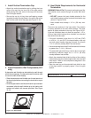
• Pull enough wire into the valve compartment to easily reach
the junction box location.
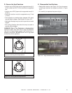
• Remove the screw attaching the junction box to the junction
box bracket and set it aside.
• Route the wire through the knockout in the junction box
bracket.
• Wire the junction box and reattach it to the bracket by
inserting the tab in the slot and attaching with screw
previously removed. Ensure that a Romex connector is
used to attach the electrical wires to the junction box.