


Heat & Glo • ST-36TR-IPI, PIER-36TR-IPI • 2176-900 Rev. F • 8/1154
GAS CONTROL
VALVE
VARIABLE
REGULATOR
FLAME CONTROL
SOLENOID
WASHER
VARIABLE
REGULATOR
VARIABLE
REGULATOR
WASHER
PLUNGER
JAM NUT
NUT
SCREW
KNOB
SOLENOID
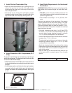
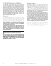
Figure 12.4 Install the Flame Solenoid
F. Install the Flame Solenoid
• Remove the screw and knob from the variable regulator
and discard.
• Remove the nut from the regulator and discard.
• Remove the bag containing a washer and blue and red
plungers from the side of the fl ame control solenoid.
• Place washer on fl ame control solenoid.
• Insert the correct plunger (blue - natural gas, red -
propane) into the fl ame control solenoid.
• Thread the fl ame control solenoid with correct plunger
into the thread hole in the variable regulator. Turn into
valve approximately two full turns. Do not tighten or
damage may occur.
• Connect orange wires from control box to the fl ame
control solenoid.
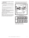
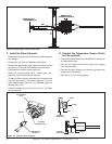
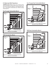
G. Connect the Temperature Sensor Switch
for Fan (optional)
• Find the two yellow wires from the WSK-MLT control box
and disconnect them.
• Connect one yellow wire to one jumper wire hanging
from the thermodisc.
• Connect the other yellow wire to remaining jumper wire
hanging from thermodisc.
• See Figure 12.2 for wiring diagram.
WHT
BLK
WHT
BLK
WHT
BLK
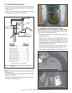
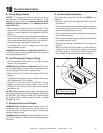
EMBER LIGHT
CONNECTOR BLOCK
BULB SOCKET
ASSEMBLY (3)
Figure 12.3 Ember Light Connector Block Detail