


Heat & Glo • ST-36TR-IPI, PIER-36TR-IPI • 2176-900 Rev. F • 8/1152
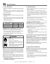
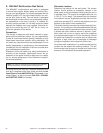
E. WSK-MLT Multifunction Wall Switch
The WSK-MLT multifunctional wall switch is designed
to control fl ame height, blower speed and auxilary func-
tions on your gas fi replace. For models equipped with the
Intellifi re system (IPI), the cold climate function can con-
trol the pilot fl ame as well. The wall switch is equipped
with thermostat functions which can automatically control
the temperature in the room in which it is installed. An
auxiliary function provides 110-120 VAC source for added
features the fi replace may have installed. Electrical rat-
ings for the control box are 110 VAC, 60 Hz, and is re-
quired for operation of this device.
Precautions
This remote is tested and safe when installed in accor-
dance with this installation manual. It is your responsibility
to read all instructions before starting installation and to
follow these instructions carefully during installation. Do
not install any components that may be damaged. Do not
modify, disassemble, or substitute any of the components
included with this kit. Installation of this unit must be done
by a qualifi ed service technician.
Placement of this wall switch may affect performance or
accuracy of the automatic (thermostat) control. An as-
sessment of the space should be done prior to installa-
tion for optimal performance. See “Determine Location”
for recommendations.
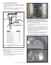
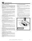
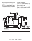
Determine Location
Determine the location for the wall switch. The chosen
location should provide an accessible location in the
same space as the gas fi replace. Never place this unit in
a separate room. The control wire supplied with this unit
is 12 ft (3.7 m) in length. The distance from the fi replace
to the switch may be lengthened provided that the wire
used never exceeds 50 ft, and that the distance from the
fi replace to the switch never exceeds 30 ft.
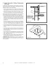
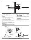
The switch should be mounted into a listed electrical junc-
tion box. The junction box should be dedicated to this wall
switch. Never install this wall switch into a junction box that
is shared with other electrical service or devices. If pos-
sible, install this unit on an interior wall of the residence
at a recommended height of 5 ft from the fl ooring. Should
the switch be installed on an exterior wall, be certain wall
insulation is kept intact and not damaged or dislodged
during the installation of the electrical junction box.
For exterior wall installations, it is recommended that the
junction box be sealed with caulking material. This will
minimize heat loss through this location and improve the
accuracy of the automatic (thermostat) operation.
All wiring should be done by a qualifi ed electrician and
shall be in compliance with local codes and with the Na-
tional Electric Code ANSI/NFGA No. 70- current (in the
United States), or with the current CSA C22.1 CANADI-
AN ELECTRIC CODE (in Canada).
Note: The electrical junction box provided with the fi replace
must be wired with 110 VAC before installing this kit.