


Heat & Glo • 6000TRS-CE • 2049-900 Rev. Q • 2/11 9
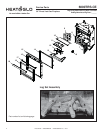
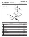
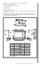
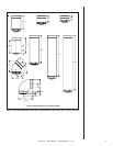
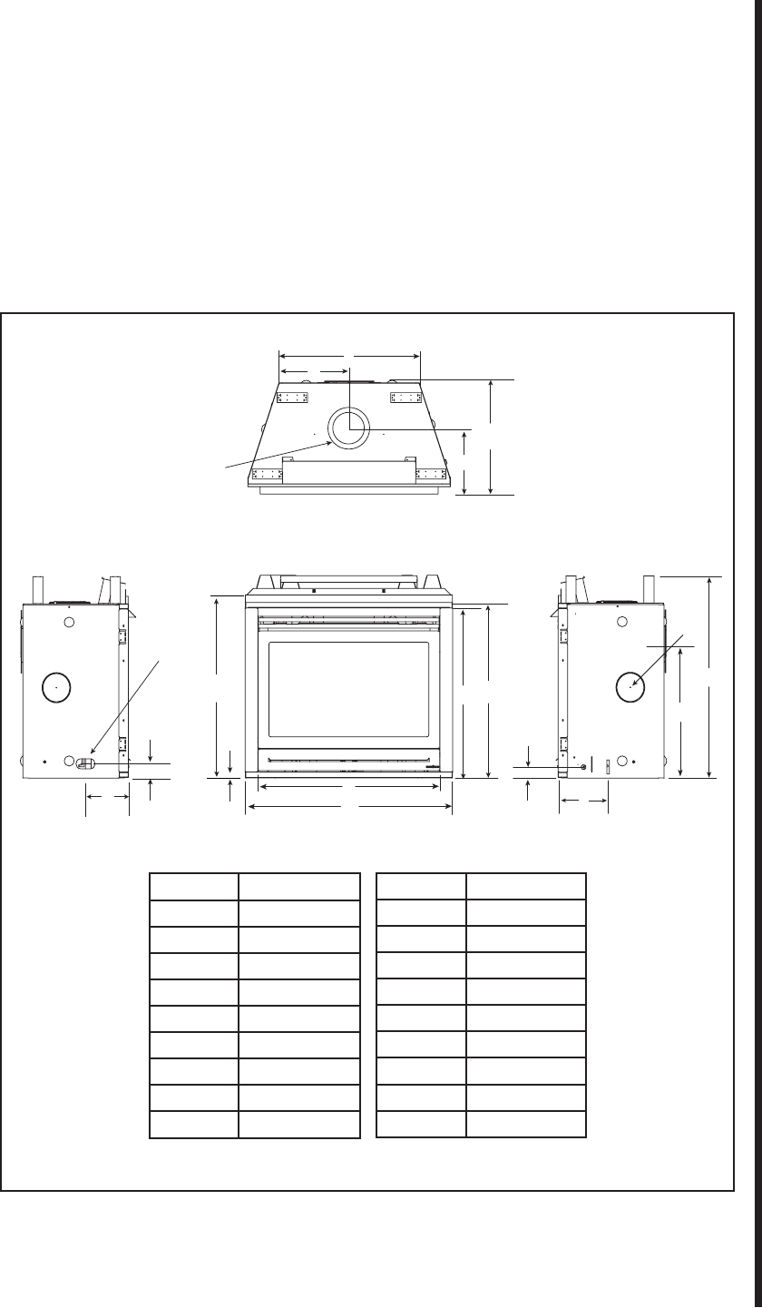
Figure 1. Diagram of the 6000TRS-CE
When planning a fi replace installation, it’s necessary to determine:
• Where the unit is to be installed.
• The fl ue system confi guration to be used.
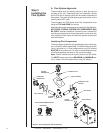
• Gas supply piping.
• Electrical wiring.
• Framing and fi nishing details.
• Whether optional accessories—devices such as a fan, wall switch, or remote control—are
desired.
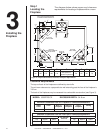
If the fi replace is to be installed on carpeting or tile, or on any combustible material other
than wood fl ooring, the fi replace should be installed on a metal or wood panel that extends
the full width and depth of the fi replace.
A
B
C
D
E
FRONT VIEW
TOP VIEW
LEFT SIDE RIGHT SIDE
F
G
H
I
J
K
L
M
O
P
GAS LINE
ACCESS
Q
R
N
C
L
C
L
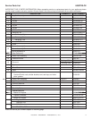
Location Centimeters
J 54,6
K 29,7
L 72,4
M 36,2
N 21,6
O73
P 21,6
Q25
R 91,8
Location Centimeters
A 104,1
B 91,8
C 85,1
D 87,9
E57
F 24,6
G 68,3
H 15,2 dia
I 101,9