


Heat & Glo • 6000TRS-CE • 2049-900 Rev. Q • 2/11 29
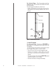
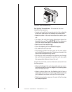
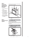
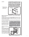
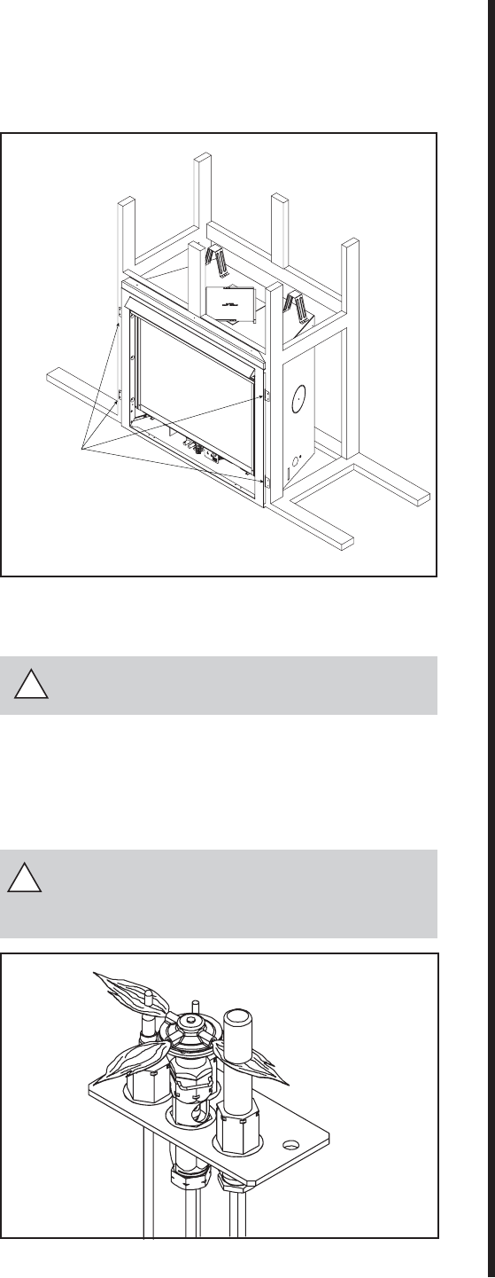
The diagram below shows how to properly position,
level, and secure the fi replace.
Step 4
Positioning,
Leveling, and
Securing the
Fireplace
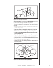
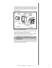
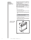
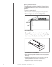
Figure 27. Gas Control System
!
!
STANDING PILOT
NAILING TABS
(BOTH SIDES)
WARNING: 230 VAC MUST NEVER BE
CONNECTED TO A CONTROL VALVE IN
A MILLIVOLT SYSTEM.
Figure 26. Proper Positioning, Leveling, and Securing of a
Fireplace
1. Place the fi replace into
position.
2. Level the fi replace
from side to side and
from front to back.
3. Shim the fi replace with
non-combustible ma-
terial, such as sheet
metal, as necessary.
4. Secure the fi replace to
the framing by nailing
or screwing.
Step 5
The Gas Control
System
WARNING: THIS UNIT IS NOT FOR USE
WITH SOLID FUEL.
Standing Pilot Ignition System
This system includes millivolt control valve, standing
pilot, thermopile/thermocouple fl ame sensor, and
piezo ignitor.