


Heat & Glo • 6000TRS-CE • 2049-900 Rev. Q • 2/11 23
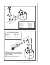
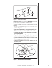
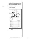
Figure 18. Flue Pipe & Firestop
For Vertical Runs - One fi restop is REQUIRED at the hole
in each ceiling through which the fl ue passes.
To install fi restops for vertical runs that pass through
ceilings:
• Position a plumb bob directly over the center of the verti-
cal fl ue component.
• Mark the ceiling to establish the center point of the fl ue.
• Drill a hole or drive a nail through this center point.
• Check the fl oor above for any obstructions, such as wir-
ing or plumbing runs.
• Reposition the heater and fl ue system, if necessary, to
accommodate the ceiling joists and/or obstructions.
• Cut a 25.4 cm X 30.5 cm hole through the ceiling, using
the fi restop pipe opening as a guide.
• Frame the hole with framing lumber the same size as
the ceiling joists.
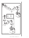
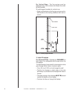
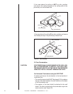
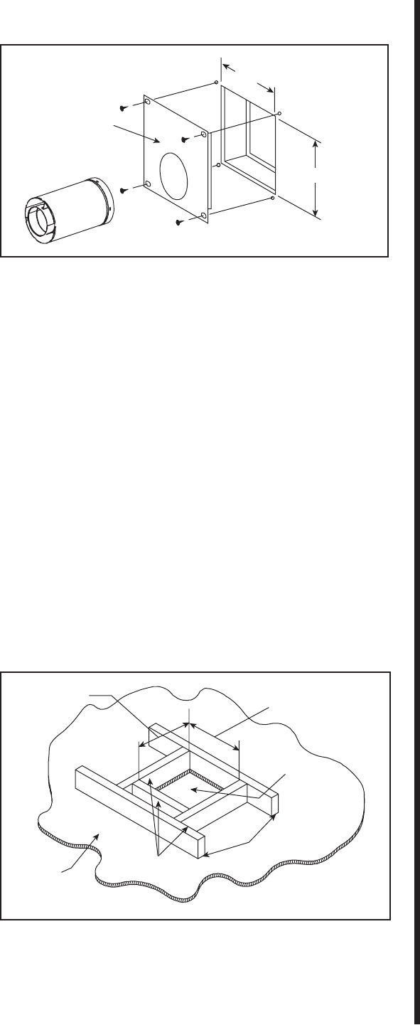
Figure 19. Hole and New Framing Members
CEILING
NEW
FRAMING
MEMBERS
EXISTING CEILING
JOISTS
CHIMNEY
HOLE
10" (25.4 cm)
)mc 4.52( ”01
10" (25.4 cm)
12" (30.5 cm)
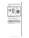
INTERIOR
WALL SHIELD