


Heat & Glo • 6000TRS-CE • 2049-900 Rev. Q • 2/11 31
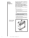
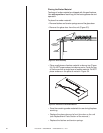
A tap is provided on the outlet side of the gas control for a
test gauge connection to measure the manifold pressure.
To measure inlet pressure, provisions must be made to
attach a test gauge to the tap immediately upstream of
the gas supply connection to the fi replace.
The fi replace and its individual shut-off valve must be
disconnected from the gas supply piping system during
any pressure testing of the system at test pressures in
excess of 60 mbar.
If the fi replace must be isolated from the gas supply
piping system by closing an individual shut-off valve, it
must be of the handle-less type.
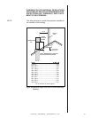
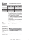
Pressure requirements for Heat & Glo gas
fi replaces are shown in the table below.
Step 7
Gas Pressure
Requirements
Natural Gas Propane Butane Natural Gas
(G20) (G31) (G30) (G25)
Inlet Pressure 20 mbar 37 or 50 mbar 30 or 50 mbar 25 mbar
Manifold Pressure 4-8.7 mbar 15.7-25 mbar 15.7-25 mbar 4-8.7 mbar
Gas Rate .54
m
3
/
h
.24
m
3
/
h
.16
m
3
/
h
.54
m3
/
h
Max. Input(NETCV) 10.0 kW 10.0 kW 9.5 kW 8.5 kW
Burner Injector DMS 33 1.8 mm DMS 51 DMS 33
Pilot Injector 51 30 30 51
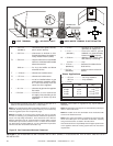
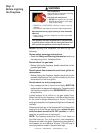
Step 8
Wiring the
Fireplace
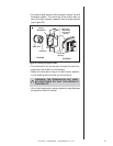
Optional Accessories
Optional remote control
kits require that 230 VAC
be wired to the factory in-
stalled junction box before
the fi replace is permanently
installed.
!
WARNING: DO NOT CONNECT 230 VAC
TO THE GAS CONTROL VALVE OR THE
APPLIANCE WILL MALFUNCTION AND THE
VALVE WILL BE DESTROYED.
NOTE: Electrical wiring must be installed by a
competent electrician.
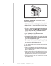
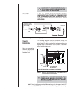
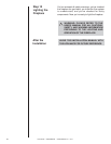
For Standing Pilot Ignition Wiring
Appliance Requirements
Wall Switch
Position the wall switch in the desired position on a wall. Run a maximum of 780
cm or less length of 0.102 cm diameter minimum wire and connect it to the fi replace
ON/OFF switch pigtails.