


Heat & Glo • 6000TRS-CE • 2049-900 Rev. Q • 2/11 21
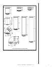
Installing Flue Components
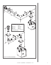
1. Attaching the First Flue Component to the Starting Collars:
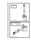
A. On the REAR of the heater
• To attach the fi rst fl ue component to the starting collars on the rear of the heater
make sure that the heater gasket supplied with the heater seals between the fi rst
fl ue component and the outer heater wrap.
• The fi rst 90° elbow installed in the fl ue system of a rear fl ueing heater MUST BE in
a vertical position.
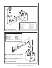
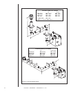
B. On the TOP of the heater
To attach the fi rst fl ue component to the starting collars on the top of the heater:
• Slide the male end of the inner fl ue of the pipe section into the inner collar on the
heater. At the same time, insert the outer fl ue into the outer collar on the heater.
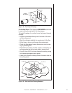
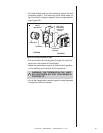
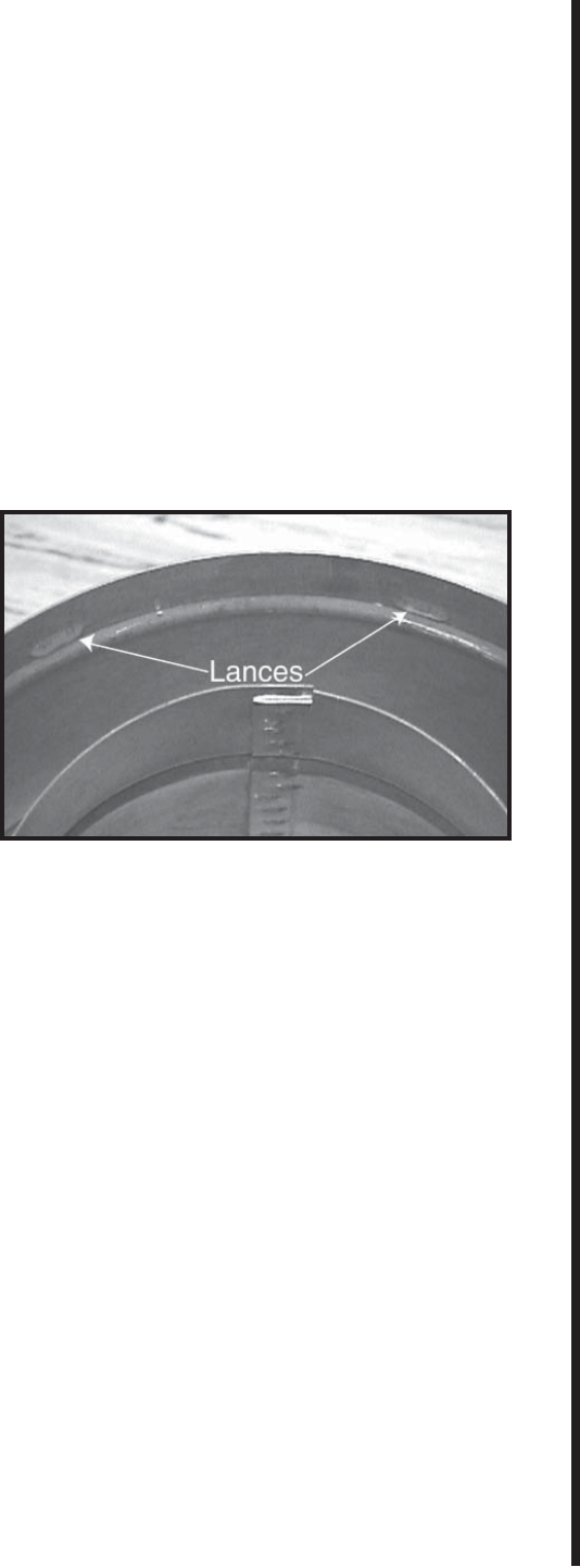
Push the fl ue section into
the appliance collar until all
the lances (see Figure 16)
have snapped in place. Tug
slightly on the fl ue to con-
fi rm that it has completely
locked into place.
• Slide the ceramic fi ber pad
over the fi rst fl ue section
and place it flush to the
fi replace. Continue to add
vent components.
WARNING: ENSURE THAT THE HEATER GASKET SUPPLIED WITH THE HEATER
SEALS BETWEEN THE FIRST FLUE COMPONENT AND THE OUTER HEATER
WRAP.
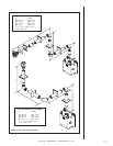
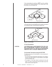
C. Continue Adding Flue Components
To continue adding fl ue components in accordance with the pre-planned fl ue system
confi guration:
• Ensure that each succeeding fl ue component is securely fi tted and locked into the pre-
ceding component in the fl ue system. NOTE: Make sure that seams are NOT aligned
to prevent unintentional disconnection.
• For elbows that are changing the fl ue direction, two screws minimum should be put in
the outer fl ue at the joint to prevent the elbow from rotating.
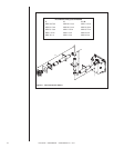
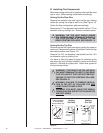
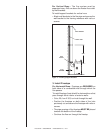
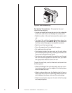
2. Install Support Brackets
For Horizontal Runs - The fl ue system must be supported every fi ve (5) feet (152.4
cm) of horizontal run by a horizontal pipe support.
To install support brackets for horizontal runs:
• Place the pipe supports around the fl ue pipe.
• Nail the pipe supports to the framing members.
Figure 16.