


34
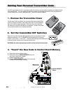
Mighty Mule 352
ON/OFF
– o
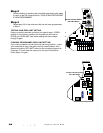
Battery Harness Wires
Transformer or Solar Wires
Receiver Wires
Communication Cable (LINK)
Accessory Wires
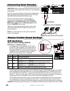
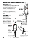
Neatly arrange all
wires to lay flat as
they come out of
the opener.
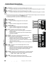
Mighty Mule 352
Master Opener
Wire Routing
Routing Pin
20 amp fuse
20
The master opener's battery harness wire has an in-line 20 Amp fuse
that must be placed inside the opener prior to closing the access
panel. The illustration to the right shows the best place-
ment for the battery harness wire, connector and in-line
fuse, communication cable, receiver wire, transformer
or solar panel and any accessories that have been
installed. All wires must be routed down the sides of the
opener and flatly out the slot in the back of the opener.
It is IMPORTANT that the wires lay flat and run inside the
routing pins at the back of the opener and out the slot
without being pinched when the control board access
cover is replaced. See the illustrations to the right and
below.
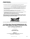
Wire Slot
To avoid stripping screw
holes - tightening screws
by hand with a hand held
screwdriver is recommended.
If you have any questions please
call GTO Technical Service at
1-800-543-1236.
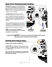
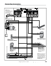
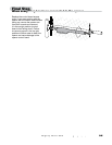
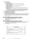
Second Opener
Master Opener
ON/OFF
– o
Battery Harness Wires
Communication Cable
Neatly arrange
both wires to lay
flat as they come
out of the opener.
Mighty Mule 352
Second Opener
Wire Routing
Routing Pin
The battery harness and
communication cable must be
routed down the sides of the opener
and flatly out of the slot in the back
of the opener.
It is IMPORTANT that the wires lay
flat and run inside the routing pins
at the back of the opener and out
the slot without being pinched when
the control board access cover is
replaced. See the illustrations to the
right and below.
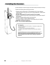
Routing Wires Through The Access Panel