


Mighty Mule 352
15
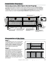
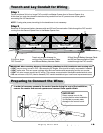
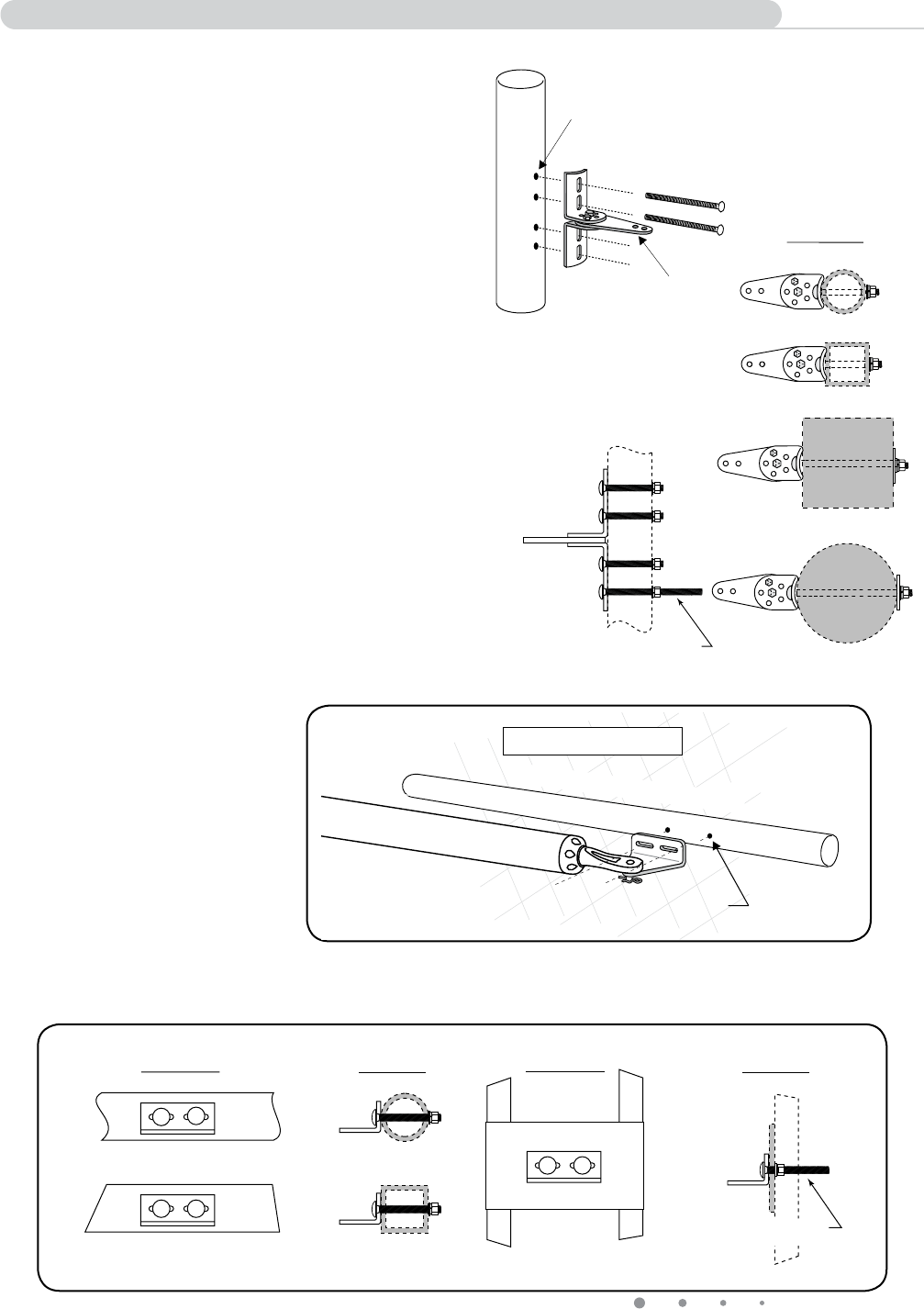
Installing the Post Bracket Assembly and Gate Bracket
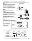
Step 7
Mark reference points for bolt holes on the fence
post through middle of bracket slots. Marking
reference points in this manner allows room for
adjustment when mounting the post bracket
assembly and gate bracket. After marking your
reference points, remove the opener and brackets
from the fence and gate.
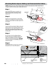
Step 8
Drill
3
/8" holes into fence post as marked.
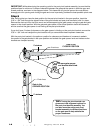
Step 9
Fasten post bracket assembly to the fence post
using (4)
3
/8" x 8" bolts, washers, lock washers,
and nuts (provided). Remove excess bolt length
extending beyond the tightened nuts with a hacksaw
or bolt cutters.
NOTE: In cases where the fence post has a
diameter larger than 6", threaded rods or carriage
bolts longer than 8" (not supplied) must be used.
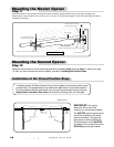
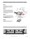
Step 10
Mark reference points for bolt holes on the gate
cross member through middle of gate bracket slots.
Drill
3
/8" holes into the gate
cross member as marked.
Mount gate bracket using (2)
3
/8" x 3" bolts, washers, lock
washers, and nuts (provided).
Cut off excess bolt length
extending beyond the
tightened nuts.
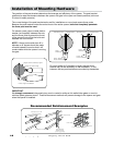
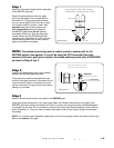
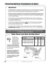
Gate Bracket Mounting Examples
Round Tube & Chain Link Gate
Square Tube Gate
Mounting Plate
Created for
Decorative Gate
(required but not
supplied)
Remove excess bolt length
with hacksaw or bolt cutters
FRONT VIEW
SIDE VIEW
FRONT VIEW
SIDE VIEW
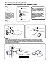
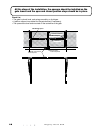
Round Metal Post
Round Wood Post
Square Metal Post
Square Wood Post
Remove excess bolt length
with hacksaw or bolt cutters
SIDE VIEW
TOP VIEW
EXAMPLES
Post Bracket
Assembly
Mark fence post through
middle of bracket slots
and drill 3/8" holes
Gate In Open Position
LEVEL horizontal cross member
Mark cross member through middle of
gate bracket slots and drill 3/8" holes