


32
Mighty Mule 352
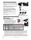
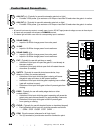
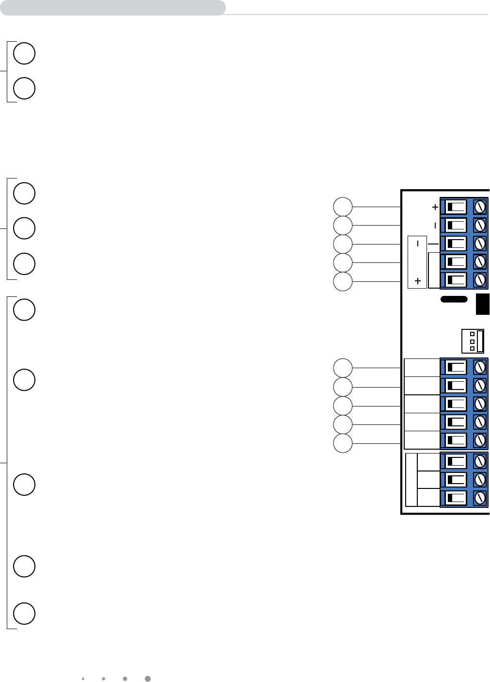
1 AUX OUT (+): (Typically for use with automatic gate lock or light)
• Provides 12Vdc power @ a maximum of 2 Amps or less than 25 watts when the gate is in motion.
2 AUX OUT (-): (Typically for use with automatic gate lock or light)
• Provides 12Vdc power @ a maximum of 2 Amps or less than 25 watts when the gate is in motion.
3 SOLAR PANEL (-)
• Input for 18-22Vdc charge power from solar panel
4 18 VAC
• Input for 18-22Vac charge power from transformer
5 SOLAR PANEL (+):
• Input for 18-22Vdc charge power from solar panel
• Input for 18-22Vac charge power from transformer.
6 EXIT: (Typically for use with exit loop or wand)
• Activation of this input will open the gate if it’s not already at
the open position
• Activation of this input while at open limit will restart the auto
close time (if enabled).
7 SAFETY: (Typically for use with photo beam device, loop
detector or other non-contact sensors)
• Activation of this input while the gate is closing will cause
the gate to stop and return to the opened position.
• Activation of this input while the gate is opening has no effect
(gate will continue to open).
• Activation of this input while gate is idle will prevent gate from
closing.
8 EDGE: (Typically for use with safety edge device or other
contact sensor)
• Activation of this input while the gate is operating will cause the
gate to stop and reverse direction for approximately 2 seconds.
• Activation of this input while gate is idle will prevent gate
from opening or closing.
9 CYCLE: (Typically for use with doorbell button or hardwired keypad)
• Each activation at this input will cycle the operation as follows:
….→ OPEN → STOP → CLOSE → STOP → OPEN → …
10 COM: Circuit common (reference for all logic input)
• Two (2) terminals to provide extra common connection point.
3
1
6
4
5
7
8
9
10
1
ON
2 3 4
15
CHARGING
POWER
RF
PULL-PUSH
MODE1
MODE2
LOCK/BEACON
OFF 120
MIN MAX
STALL FORCE
CLOSE TIME
SET
LIMIT
LEARN
REMOTE
AUX
OUT
SOLAR
PANEL
18VAC
RCVR
GRN
BLK
RED
EXIT
SAFETY
EDGE
CYCLE
COMMON
LINK
2
Control Board Connections
LOCK OUTPUTSCHARGE POWER INPUTSACCESSORY INPUTS
NOTE:
• Allcontrolinputsaredry-contact,normallyopen,inputs.DONOTapplyexternalvoltagesourcestotheseinputs.
• AllinputsareconnectedwithrespecttoCOMMON terminal.
• Thestatuslightwillblinkoncewhenitscorrespondinginputisactivated.