


26
Mighty Mule 352
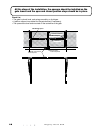
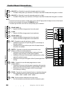
DIP Switch #4 - Lock/Beacon
This DIP selects the mode of operation of the "AUX OUT" terminal. The OFF (factory) setting is selected
when the Mighty Mule Automatic Gate Lock is used with the Mighty Mule 352. The RED wire from the
lock is connected to the "AUX OUT +" terminal and the BLACK wire from the lock is connected to the
"AUX OUT –" terminal. Factory default-(OFF position provides a timed pulse of voltage to the accessory
while the gate opener is activated). Lock and circuit board will be damaged if #4 is on.
The ON setting is selected when a beacon or light is used with the Mighty Mule 352. One wire from the
low voltage beacon or light is connected to the "AUX OUT +" terminal and the other to the "AUX OUT –"
terminal. (ON position provides a continuous voltage to the accessory while the gate opener is activated).
Important: Make sure your light or beacon is a 12Vdc system that draws less than 2 amps or less than 25 watts.
1
ON
2 3 4
15
CHARGING
POWER
STATUS
RF
PULL-PUSH
MODE1
MODE2
LOCK/BEACON
OFF 120
MIN MAX
STALL FORCE
CLOSE TIME
SET
LIMIT
LEARN
REMOTE
AUX OUT
SOLAR
PANEL
18VAC
RCVR
GRN
BLK
RED
EXIT
SAFETY
EDGE
CYCLE
COMMON
LINK
1
ON
2 3 4
PULL-PUSH
MODE1
MODE2
LOCK/BEACON
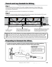
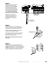
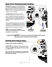
MODE 1 MODE 2
DIP #2 DIP #3 Dual Mode Sequence
OFF OFF
Single Gate Mode
ON OFF MASTER opens 1st, SECOND opens 2 seconds later.
SECOND closes 1st, MASTER closes 4 seconds later. (factory)
OFF ON MASTER opens 1st, SECOND opens 2 seconds later.
SECOND closes 1st, MASTER closes 8 seconds later.
ON ON MASTER and SECOND simultaneously open and close.
1
ON
2 3 4
15
CHARGING
POWER
STATUS
RF
PULL-PUSH
MODE1
MODE2
LOCK/BEACON
OFF 120
MIN MAX
STALL FORCE
CLOSE TIME
SET
LIMIT
LEARN
REMOTE
AUX
OUT
SOLAR
PANEL
18VAC
RCVR
GRN
BLK
RED
EXIT
SAFETY
EDGE
CYCLE
COMMON
LINK
Low Voltage Wire
from Solar Panel(s)
REDBLK
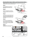
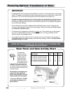
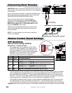
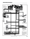
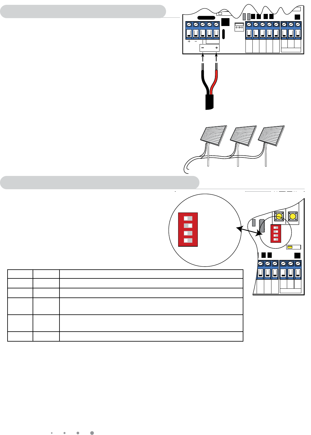
Master Control Board Settings
Connecting Solar Panel(s)
IMPORTANT: Never connect the transformer and a solar panel
to the opener control board at the same time. It will damage the
control board.
If you are using the transformer included with the Mighty Mule
352 to charge the opener battery, skip this section and go to
"MASTER CONTROL BOARD SETTINGS" below.
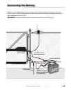
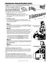
Strip
3
/16" off the ends of the low voltage wire from
the solar panel and twist tightly. Attach the RED solar
panel wire to the SOLAR terminal marked (+) and the
BLACK solar panel wire to the SOLAR terminal marked
(–) on the MASTER control board.
Tighten set screws against exposed end of wires. A dab
of household petroleum jelly on each terminal will help
prevent corrosion.
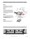
NOTE: For multiple panels wire the panels in parallel as
shown in this diagram.
RED
RED
BLACK
BLACK
attach BLACK to negative (–) solar terminal on control board
attach RED to positive (+) solar terminal on control board
Solar Panels connect in PARALLEL
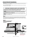
DIP Switches
Main DIP Switch Settings (MODES)
DIP Switch #1 - Push/Pull-to-Open
If your gates open into the property the DIP Switch
is set to OFF (factory default). If your gates open out
from the property the DIP Switch must be set to the
ON position. NOTE: if you have a Push-to-Open gate
application you will need Push-to-Open brackets
(see Push-to-Open Instructions on page 36).