


24
Mighty Mule 352
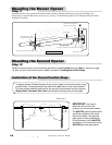
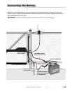
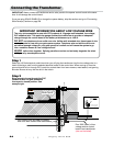
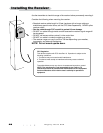
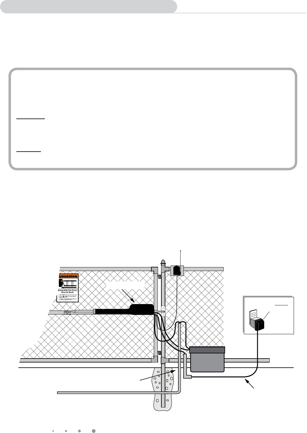
Connecting the Transformer
GTO indoor
Transformer
(surge protector
not supplied)
Run 1000' (max.) of low
voltage wire to control
board from transformer
(wire not included).
PVC conduit (not included) to protect
wire from lawn mowers and weed eaters.
Master Opener
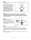
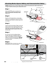
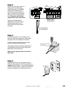
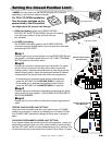
Step 1
Select the 120 Volt electrical outlet into which you will plug the transformer. Lay the low voltage wire in a
trench following a path from the selected electrical outlet to the control box. Wires coming up from the
ground should be run through PVC conduit to protect them from lawn mowers, weed eaters, and grazing
animals. Be sure to bury the wire laid in the trench.
Step 2
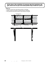
Bring enough wire up through the PVC
conduit to allow for gate movement
from open to closed position. See
example right.
IMPORTANT INFORMATION ABOUT LOW VOLTAGE WIRE
The only wire acceptable for use with GTO products is 16 gauge multi-stranded, low voltage,
PVC sheathed wire. This particular gauge enables the transformer to provide an adequate
charge through the control board to the battery at distances up to 1000 ft.
DO NOT use telephone wire or solid core wire. Unlike multi-stranded wire, these types of wire
are inadequate for use with your gate opener system. Telephone wire and solid core wire do
not deliver enough voltage for your gate opener to function and will cause the system to go
into a condition known as "low voltage lockout."
NEVER splice wires together. Splicing permits corrosion and seriously degrades the wire's
ability to carry an adequate current.
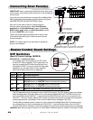
IMPORTANT: Never connect the transformer and a solar panel to the opener control board at the same
time. It will damage the control board.
If you are using SOLAR PANEL(S) to charge the opener battery, skip this section and go to "Connecting
Solar Panel(s)" section on page 26.