


Mighty Mule 352
25
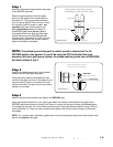
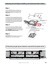
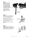
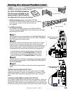
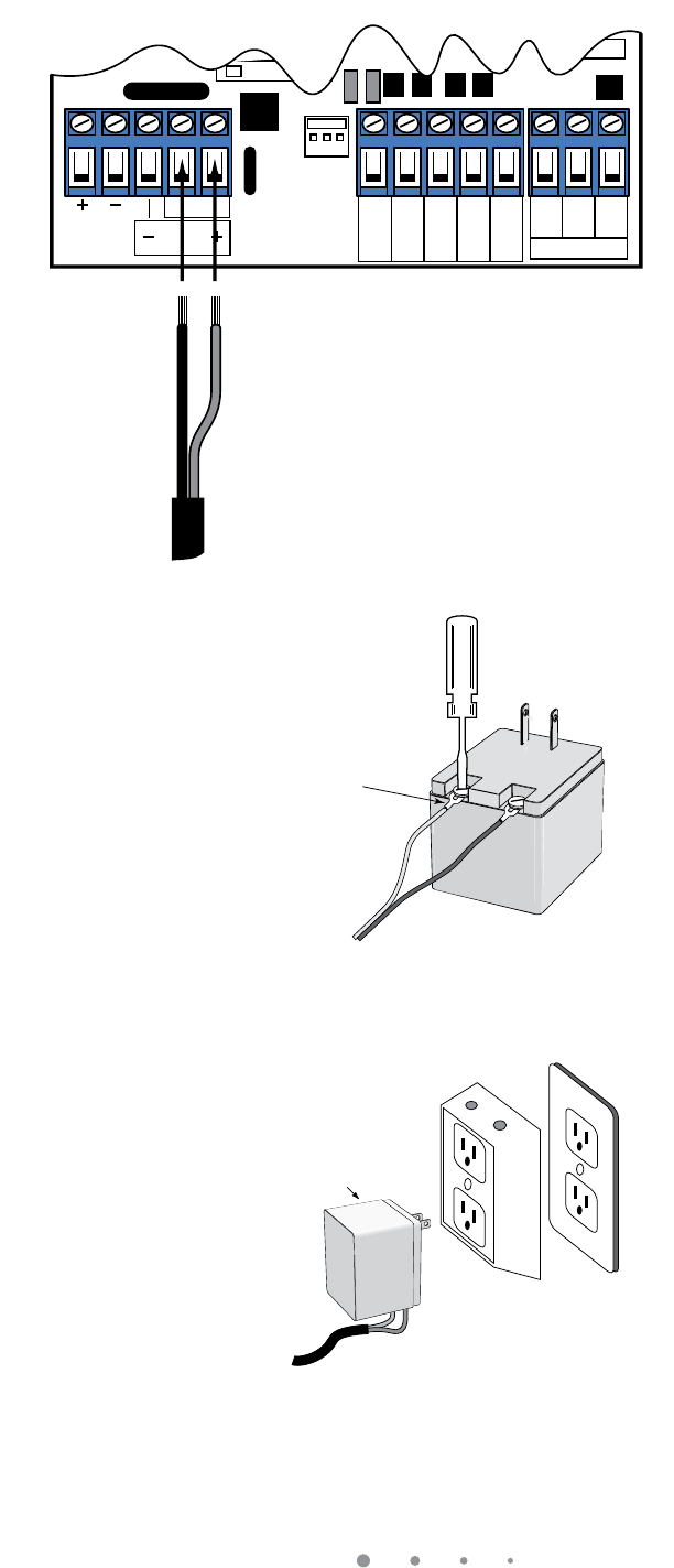
Step 5
Plug the transformer into the electrical outlet.
(Use of a surge protector with the transformer is
strongly recommended - not included) If electrical
outlet is located outdoors, outlet and transformer
should be protected by a weatherproof cover.
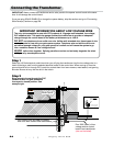
Step 4
At the AC outlet strip
1
/2" of insulation from
the ends of the low voltage wire. Attach these
stripped ends to the transformer terminals.
A dab of household petroleum jelly on each
terminal will help prevent corrosion.
We suggest crimping a spade tongue terminal
(not provided) to the end of each wire before
attaching it to the transformer.
Make sure the exposed wires do not touch
each other!
AC@53>@=B31B=@
Transformer
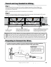
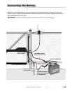
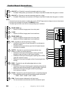
Step 3
Strip
3
/16" off the ends of the low
voltage wire and twist tightly.
Insert these ends to the 18 VAC
terminal block located on the
control board (see illustration at
right). The wires can be inserted
into either terminal regardless of
color. Be certain not to let the
exposed wires touch each other!
Tighten set screws against
exposed end of wires. A dab of
household petroleum jelly on
each terminal will help prevent
corrosion.
Spade Tongue Terminal
(not provided)
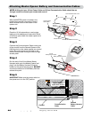
1
ON
2 3 4
15
CHARGING
POWER
STATUS
RF
PULL-PUSH
MODE1
MODE2
LOCK/BEACON
OFF 120
MIN MAX
STALL FORCE
CLOSE TIME
SET
LIMIT
LEARN
REMOTE
AUX
OUT
SOLAR
PANEL
18VAC
RCVR
GRN
BLK
RED
EXIT
SAFETY
EDGE
CYCLE
COMMON
LINK
Low Voltage Wire
from Transformer
Master Arm
Control Board